Continue to Site

Welcome to EDAboard.com

Welcome to our site! EDAboard.com is an international Electronics Discussion Forum focused on EDA software, circuits, schematics, books, theory, papers, asic, pld, 8051, DSP, Network, RF, Analog Design, PCB, Service Manuals... and a whole lot more! To participate you need to register. Registration is free. Click here to register now.

variable voltage regulator Lm317

Status
Not open for further replies.

aliraza786

Full Member level 4
Joined
Nov 10, 2009
Messages
210
Helped
14
Reputation
28
Reaction score
14
Trophy points
1,298
Location
Lahore, Pakistan, Pakistan
Activity points
2,914
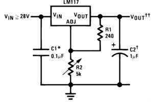
i have joined a circuit as shown in the datasheet everything works fine but when i conect the load to the output volatge drop from 9 to 3 volts and only variable from 0 to 3 but when i disconeet the load it again goes to 9..i know this problem is due to the current...but how to overcome this......my input volatge is 12.. here is the circuit.
70_1316069158.jpg
 

Assuming that the circuit is correctly assembled as shown in the schematic it is probably the power supply, it can't provide the output current you ask for and the voltage drops rapidly.
Check the power supply and load current specifications and ensure that the power supply can provide more current that the load requires.

Alex
 

If he wants a regulator that can provide more current (and his input power supply is able to provide that current) he can use a device like LM350 for 3A or LM338 for up to 5A.

Alex
 

How much current you are drawing. LM317 has inbuilt current limiter.around 1.5A. If current excceesd. It decreases output voltage to limit out put current.
21_1316072161.gif
 
Last edited:

This reminds me of my (mis)adventure.....I forgot that pinout of 317 is different than 7805...and wasted some trying to figure out the problem
I know that this happens with a lot of people....so please first make sure that the circuit is wired properly.
 

Embedded_Geek
according to your design we make volatge variable by lm317 and increse current by trnasistor...mean the main thing which increae the current is transistor now my question is that if we remove lm317 and insert a simple volatge divider by one constant resistance and then the other one is variable and the output volatge is fed to the bases of the transistor does this also work ..?? becuse a function of lm317 is only for variable volatge source current is increasing by transistors....
 

The function of regulator is voltage regulation. It decreases or increase feed acording to load, input voltage. Your circuit will not do that.
 

that if we remove lm317 and insert a simple voltage divider by one constant resistance and then the other one is variable and the output voltage is fed to the bases of the transistor does this also work ..??

It is not so simple because the transistor needs a current in the base which is propositional to the output current, the more current you give to your load the more current it will need from the resistor divider and this will create a voltage drop and the divider voltage will change.
In addition a voltage divider has a fixed division factor, if the input voltage increases it will just provide more voltage to the transistor base and the transistor output will get higher too.

This is why what you describe actually uses a constant voltage (zener) and a resistor, the output of the divider can remain constant while the input voltage and output current are is specified limits.
Tutorial: Transistor-Zener Diode Regulator Circuits

But even in that case there is no feedback from the output, you give a voltage to the transistor and you expect it to have a specific output but what if it doesn't, how can you know?
This is why we use feedback from the output to the control device so that any "misbehavior" or the transistor can be compensated.
Op-Amp Voltage Regulator Circuit

Alex

---------- Post added at 11:45 ---------- Previous post was at 11:42 ----------

If you want more reading on regulators
On Semiconductors Linear & Switching Voltage Regulator Handbook. HB206/D
**broken link removed**

Alex
 
thanks Alex i wana ask one more question...bjt is a current controlled device...if we use fet which is volatge controlled device then my idea of volatge devider will work or even then it has the same problem as you describe...
 

you will not be able to control the output of the mosfet using a voltage in the input, it doesn't behave like the transistor so it can only be controlled with feedback.
Mosfets are used as pass element in LDO (low drop) regulators
https://focus.ti.com/download/trng/docs/seminar/Topic 9 - Understanding LDO dropout.pdf

Alex

---------- Post added at 18:02 ---------- Previous post was at 17:37 ----------

Actually that is note entirely true, for example if you connect a Nmosfet with the drain in the positive supply and the load to the source and you drive the gate with a voltage you will get an output to the source proportional with the gate voltage but the gate to source voltage difference is highly device dependent (mainly from the gate threshold voltage ) and I think temperature too.
In reality I haven't seen such a circuit and I don't think it is usable.
While in a transistor (emitter follower) the output voltage has a difference of about 0.7v with mosfets it can be 1v,2v,3v,4v,5v it depends on the device so you can't base your regulator on that.

Alex
 

HI ali,
because a function of lm317 is only for variable volatge source current is increasing by transistors....
The function of LM317 is not only for variable voltage. It regulates the voltage relative to the demand of load and ultimately controlling the bases of the output transistors. These transistors are added to give more current under the control of LM317. If you want I can give you a circuit for 0-30 volts and 20 amperes regulated.
 

Status
Not open for further replies.

Similar threads

Part and Inventory Search

Welcome to EDABoard.com

Sponsor

Back
Top