Continue to Site

Welcome to EDAboard.com

Welcome to our site! EDAboard.com is an international Electronics Discussion Forum focused on EDA software, circuits, schematics, books, theory, papers, asic, pld, 8051, DSP, Network, RF, Analog Design, PCB, Service Manuals... and a whole lot more! To participate you need to register. Registration is free. Click here to register now.

Variable Resistor in Line follower IR sensors

Status
Not open for further replies.

amirtafrishi

Junior Member level 1
Joined
Dec 16, 2011
Messages
19
Helped
0
Reputation
0
Reaction score
0
Trophy points
1,281
Activity points
1,449
Dear Friends
I am making the PID line follower robot with LPC1768 cortex-m3.Also I am using NCY70 IR sensor. I’ve become confused about circuit of IR sensor for connecting it to ADC of my micro. I’ve seen a variable resistor on most of the circuit diagrams but when I look at the ready IR sensor array from special company, I can’t see any variable resistor in it. Can anyone tell me how they remove these variable resistors in circuit diagram?
This is the pure circuit in most of websites: http://daneshnameh.roshd.ir/mavara/img/daneshnameh_up/9/97/esquemaCNY70.gif
However this is the link of that company makes it in package: http://www.pololu.com/catalog/product/960
Lastly, if you could tell me clear & complete circuit scheme I would be thankful, because i want to make PCB board of that :)
Best Wishes...!
 

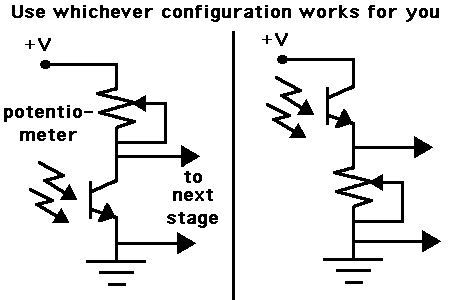
Typical use of a phototransistor is shown in the schematic below.

You will have to experiment to find the arrangement that works best for your device, in the application you are using it.

Since you are using an ADC, you don't need the op amp shown in your first diagram.

Adjust the potentiometer high and low, to find a proper operating range for light and dark conditions in your project. Take care not to let too much current go through the phototransistor, or to the next stage.

- - - Updated - - -

56_1344555736.gif
 
Thanks for your noteworthy advice. One more thing, i want to put .1uf capacitor between v+, GND for each IR sensor for preventing noise do u think it is worth it?

- - - Updated - - -

Aw... i forgot to ask. I’ve used 220ohm for IR LED but I don't know how choose between 10-22k resistor for photo NPN.TO be clear, My sensor going to placed .9-1 cm from surface. I can't recognize which amount is ideal for Photo NPN; high resistor is good or low?
I would be happy if you could answer me quickly :)
 

i want to put .1uf capacitor between v+, GND for each IR sensor for preventing noise do u think it is worth it?

Usually we first try to get the important parts assembled and working, or semi-working. If you find that noise is a problem, then you can start adding capacitors.

I don't know how choose between 10-22k resistor for photo NPN.

We can't know since we don't know the characteristics of your phototransistor when it's facing the floor. A potentiometer will let you make adjustments. Experimentation is the only path to success while you are developing a project like this.

My sensor going to placed .9-1 cm from surface.

I had a line-follower robot called a Movit (commercial kit). It would not follow a line properly, or it would lose track of the line easily.

In an effort to make it work, I had to break the neck which held the sensors, and then glue it back so the sensors were snug to the floor. The robot worked very well after that. In fact it would follow the crevice between wood floorboards.

Before then the sensors were probably not more than 1/10 inch above the floor. That's how much difference there was between success or failure.

I can hardly imagine how the Movit manufacturer thought they could get away with it.

So if you want to put the sensors 1 cm high, then you will need to make custom optical sights for them, to focus on a narrow line 1 cm below.
 
Status
Not open for further replies.

Similar threads

Part and Inventory Search

Welcome to EDABoard.com

Sponsor

Back
Top