Continue to Site

Welcome to EDAboard.com

Welcome to our site! EDAboard.com is an international Electronics Discussion Forum focused on EDA software, circuits, schematics, books, theory, papers, asic, pld, 8051, DSP, Network, RF, Analog Design, PCB, Service Manuals... and a whole lot more! To participate you need to register. Registration is free. Click here to register now.

Variable load for three-phase inverter

Status
Not open for further replies.

mike buba

Member level 2
Joined
Nov 17, 2013
Messages
50
Helped
0
Reputation
0
Reaction score
1
Trophy points
1,286
Activity points
1,707
Hi all,

I want to test three-phase inverter from Pmin to Pnominal.
The simplest, but the most expensive solution is by using laboratory variable load.
Another solution is by using arrangement of three-phase loads and switches (something often used in simulations).
Inverter back-to-back test is out of the question since I have only one inverter.

What about three-phase induction motor?
At no load I can get current corresponding to the reactive power (i.e. losses). But how can I increase the torque (current) of the motor?
I need constant voltage and frequency output (3×400 V, 50 Hz).
I am not sure how B2B with two motors supplied from the same inverter would work, but I assume it has to do something with frequency (speed) control.
Is there anything else I can use as a load for the motor shaft.

Or any other load/solution. But in the price range of a motor.
btw. inverter (motor) power is up to 2 kW (≈ 2 HP)!
 

Such an ingenious solution :smile:
Thanks!
 

Hi,

I dont understand: you requested "variable" load...

* are the bulbs "variable"?

additionally:
* what about the temperature dependent resistance of the bulbs? Doesn´t this cause problems?
* the bulbs are a pure ohmic load, but a motor usualy is a complex (inductive) load. Is the test valid then?


Klaus
 

Hi Klaus,

I need load to test three-phase inverter output. Using a motor was just one of ideas.
But I do not know how to load (increase a torque) of a (2 kW) motor?

Under variable load I mean load that can be changed in several steps.
Combination of light bulbs and simple on/off switches (2 A, 230 V) connected in parallel seems OK.

Kind regards
 

Motor test stands in industry are using either load machines (generators with variable electrical load), or mechanical brakes. I remember both have been used in the electrical power lab that I passed in my second year. I can imagine a number of other mechanical loads which can serve your purpose (e.g. pumps with variable restriction).

For the dynamical test of motor inverters, real motors or electronic motor simulators are often wanted. A simple resistive load can at least test continuous service. Incandescent bulbs have the specific disadvantage of low (e.g. 1/10) cold resistance.
 

The problem with incandescent light bulbs is their inrush current which will most likely trip the inverter protections.

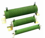
You can always do a resistor bank using low cost ceramic power resistors, like these:

resistors.png

You can vary the load by switching resistors in and out with low cost switches.

Of course these are unity power factor only. But at least will give you an idea that the powertrain is operating properly under load.
For lagging PF you may require a mechanically-unloaded induction motor to provide the reactive power in parallel with the resistor bank which will provide the vast majority of real power.
 

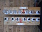
Guys, its not that difficult to arrange a bunch of light bulbs and switches, even bulbs of differing wattages, to progressively switch in and out as much test load as may be required.

I built these up some time ago to test a solar MPPT boost converter.
Seven lamp sockets switched 4 - 2 - 1 in binary is pretty convenient.

Definitely red neck engineering, and definitely a variable load.
And it was perfectly adequate for the testing I wished to do at the time.

Load.jpg
 

Status
Not open for further replies.

Part and Inventory Search

Welcome to EDABoard.com

Sponsor

Back
Top