Continue to Site

Welcome to EDAboard.com

Welcome to our site! EDAboard.com is an international Electronics Discussion Forum focused on EDA software, circuits, schematics, books, theory, papers, asic, pld, 8051, DSP, Network, RF, Analog Design, PCB, Service Manuals... and a whole lot more! To participate you need to register. Registration is free. Click here to register now.

Variable bidirectional current source

Status
Not open for further replies.

Mehdi1357

Member level 2
Joined
Jan 18, 2008
Messages
50
Helped
1
Reputation
2
Reaction score
0
Trophy points
1,286
Location
the Earth
Activity points
1,690
variable current source

Hi
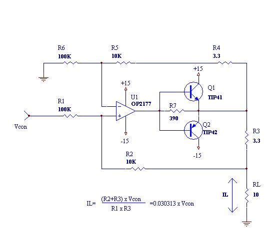
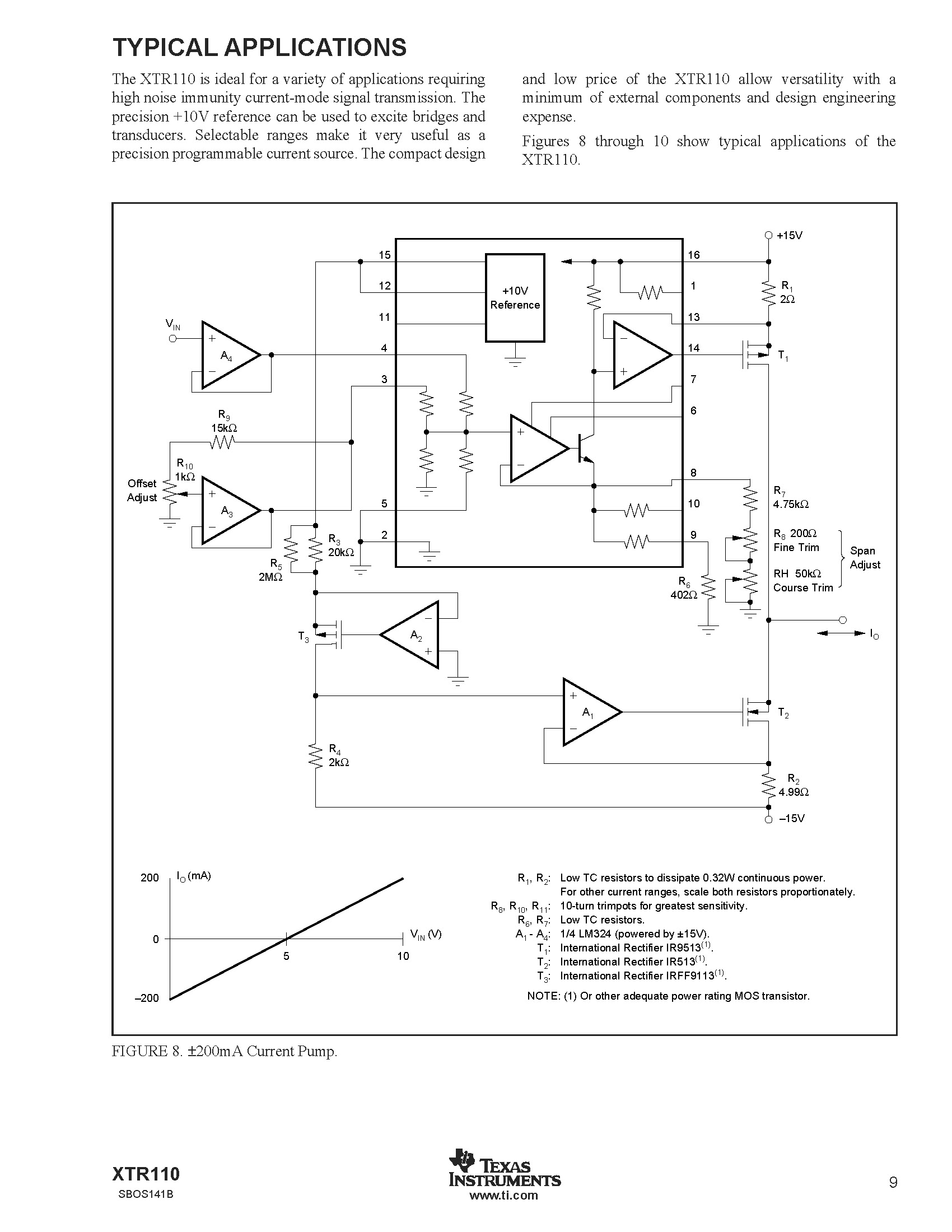
I'm going to design a precision bidirectional current source that it's current should be variable by a control voltage (I use a 24bit digital to analogue converter to do this).my load resistance is 10 Ohms and current source should be capable to sink and source a variable current between -300 to +300 mA through it.
I searched in many sites and many application notes but I have found a little information about that and I think they are very poor.
I want to know,is there a strong and practical idea to do that (Design with Op amp or an integrated circuit is better for me). While I know , maybe a current booster should be placed at the last stage (or output of op amp ) of current source.
:?:
 

bidirectional current source

You didn't clarify, what's your particular problem in designing the current source respectively the output amplifier. Obviuosly, the voltage and current range goes beyond the limits of usual OPs. You may want to use special power OPs (e.g. from Apex) or integrated audio amplifiers.

Regarding the intended topology, it would be more easy, if you can accept a floating load at the benefit of a ground referenced current sense resistor. Otherwise, a floating sense resistor with a differential amplifier would be needed.

The principal circuits for both types of current sources can be found in electronic circuit text books or manufacturer applications literature. The problems are with the detail specification and effects as offset, drift, stability, bandwidth limitation. But you didn't specify any requirements yet.
 

bi-directional current source

You didn't clarify, what's your particular problem in designing the current source respectively the output amplifier

I would like to express my gratitude to your view points. I want to generate a precision variable current between +/-300mA to calibrate a device with input impedance of 10 Ohms. It may happen the RL to be float (high impedance) one pin of RL is being connected to ground .Thermal and current stability is a important matter for me. (I will use very precision resistor that have very small TCR).

I think perhaps a bidirectional current source is a good idea to do that. So I need to find a V to I converter.

I have found a simple circuit designed with a precision Op amp But my current range is beyond the limit of this op amp , so I put two transistors in the output of the op amp (Current booster). The figure illustrate my design that I simulated it in Proteus software and it worked properly.
The Vcon is ultra precision voltage that generated from a 24 bit digital to analog converter (between +/-10V).

Please tell me the answer of the following questions:
1-Is this a good circuit in my application?
2-I don’t understand Why is There a positive feedback in this design?
3-Do you have a better idea or circuit to do that?
40_1244387510.jpg
 

variable current source circuit

It's a good circuit, generally. The main limitation of the floating sense resistor current source is the finite common mode rejection of the difference amplifier, respectively the resistor mismatch, that converts to an output resistance of the current source.

You can check the behaviour with a defined resistor mismatch and see, if it's sufficient for your requirements. Otherwise, a high CMRR instrumentation amplifier could be used as curent sense amplifier.

The circuit hasn't positive feedback. It has negative current controlled and ideally zero voltage controlled feedback.
 

curent source

I am not in love with that circuit. I think you will have some trouble around +/- 0 ma out. If you are going from a + current output thru zero to a - current, Q1 will turn off when its base voltage is getting around +0.6 volts, but Q2 will not start turning on until its base current is around -.6 volts.

If you search the litterature, I think you will find some circuits like this, but that have diodes in the transistor bias circuits that prevent this "jump" at zero cross over.

Added after 9 minutes:

Scope this out:
https://www.answers.com/topic/push-pull-amplifier

In place of the current source in the bias network, you might get away with just a resistor to -15 V
 

op amp floating current source

I am not in love with that circuit. I think you will have some trouble around +/- 0 ma out.

I appreciate you , but I think there is no any cross over distortion around zero current (remember ideal rectifier with Op amp Vf=0.7 could be ignored ) the lack of bias in two transistors has a extremely small effect in output(because a op amp have a very high gain in open loop so Vbe could be ignored). But I accept your view point , it will be very better if we bias these transistors. But it will increase power dissipation in Q1 and Q2.

I saw your link attached in end of your message it’s a good idea and I will consider these considerations but I didn’t understand why input signal is not connected between two diodes? Is there a consideration for doing that?
 

precision current generator op

Regarding the discussed cross-over distortions, as long as no dynamic and explicite linearity specifications are given, the circuit is good as is, to my opinion. The 390 ohms resistor already achieves a soft crossover. But overall linearity is affected, of course. For maximum performance, a class AB rather than class B driver should be used. Another option is to add more loop gain or use a feedback buffer in the loop.
 

bidirectional current operational amp

I searched in many documents and application notes to find a good bidirectional current source or a V to I converter. Finally I found XTR110 an integrated precision voltage to current converter . I found a egregious mistake in one of typical applications of this IC(Page 9 of datasheet). I think Drain and Source of the T2 must be exchanged with each other.
What’s your view point about that?

49_1245656397.jpg
 

Re: bi-directional current source

I was trying to replicate the circuit as I need to build a bidirectional current source. I have a small doubt regarding one connection. Op-amp output goes to base of both transistors. Both emitters are shorted but they are not connected to 390 ohm resistor. Please confirm me.

Thanks in advance

Sudipta


I would like to express my gratitude to your view points. I want to generate a precision variable current between +/-300mA to calibrate a device with input impedance of 10 Ohms. It may happen the RL to be float (high impedance) one pin of RL is being connected to ground .Thermal and current stability is a important matter for me. (I will use very precision resistor that have very small TCR).

I think perhaps a bidirectional current source is a good idea to do that. So I need to find a V to I converter.

I have found a simple circuit designed with a precision Op amp But my current range is beyond the limit of this op amp , so I put two transistors in the output of the op amp (Current booster). The figure illustrate my design that I simulated it in Proteus software and it worked properly.
The Vcon is ultra precision voltage that generated from a 24 bit digital to analog converter (between +/-10V).

Please tell me the answer of the following questions:
1-Is this a good circuit in my application?
2-I don’t understand Why is There a positive feedback in this design?
3-Do you have a better idea or circuit to do that?
40_1244387510.jpg
 

Status
Not open for further replies.

Similar threads

Part and Inventory Search

Welcome to EDABoard.com

Sponsor

Back
Top