Welcome to our site! EDAboard.com is an international Electronics Discussion Forum focused on EDA software, circuits, schematics, books, theory, papers, asic, pld, 8051, DSP, Network, RF, Analog Design, PCB, Service Manuals... and a whole lot more! To participate you need to register. Registration is free. Click here to register now.
There's jargon to unpack (is APD "Active Pixel Detector" or
"Avalanche PhotoDiode"?) but seems to me you are just
looking either for stimulus or a model of behavior. Which
one and what kinds are ancillary questions.
I have played a little with avalanche photodetectors and
with ROIC front ends but no idea which or what you are
after.
Some of what you ask seems not-the-role of a stimulus
source (or composite), like the "lineariy error" where the
error would be relative to "something" but looks like what,
based on what? A straight voltage / current source as you
asked, would be dead linear. If you want to bend that
somehow, say how.
You mean that you want to simulate the linearity of the lineup,
from "photons in" to "electrons out"? Or further, output voltage?
Do you care about the accuracy of the APD model? Do you know
that APD behavior depends critically on biasing, that sensitivity
is had right up against breakdown and you must balance on that
point for anything like "photon counting"?
A TIA is a TIA more or less. Imager TIAs have tended to be CTIAs
as the frame is constantly rasterized. But this is unsuitable for a
"staring" application as the input C can/ will charge up on leakage
given a long enough "frame period".
If I were doing this I would be applying minuscule narrow pulses
of current emulating a photon's charge separation (scaled per
physics or data) and depend on the APD model for gain and
losses. And that vetting should be done, at least the basics, first.
APD gain is kinda the whole point of using an APD, that gain is
hugely variable (and what do you know about make, bake?).
I would recommend stepping back and doing a bit of testing on
the APD model you've got (or must make) and how gain, response
match up to datasheet.
Then you can add a ccvs for your ideal TIA and see detector-
limited linearity, you can apply a current to any TIA and see the
linearity of your amplifier, and know where any improvement may
lie (or, a floor below which you can quit struggling, because APD
"is what it is").
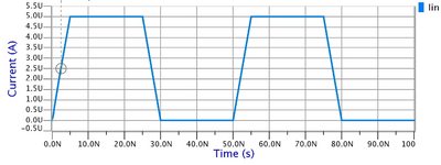
Iin in the image is varying input current from APD. can't we give direct input from isource by giving certain values in cadence?I want to have the pulse waveform that will start from 0A and then rise to 5uA and stay for next 20ns.
That plot is too ideal to be real. If you want to use such a
stimulus then ideal sources would do it. Just do not believe
that this replicates APD action, esp. gain relation to bias
and the dynamics of charge collection.
analogLib/ipulse would produce what you show, given
correct property values.
This site uses cookies to help personalise content, tailor your experience and to keep you logged in if you register.
By continuing to use this site, you are consenting to our use of cookies.