Continue to Site

Welcome to EDAboard.com

Welcome to our site! EDAboard.com is an international Electronics Discussion Forum focused on EDA software, circuits, schematics, books, theory, papers, asic, pld, 8051, DSP, Network, RF, Analog Design, PCB, Service Manuals... and a whole lot more! To participate you need to register. Registration is free. Click here to register now.

use of IR2110 for three phase Full bridge IGBT driving

Status
Not open for further replies.
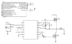
Don't get your description, 3.3 or 5V PIC supply? But running IR2110 VDD from the same supply voltage as the PIC would be O.K. anyway.

I don't know what's the matter with 341mV, is it a multimeter reading? It would be in fact meaningless. You have been complaining about PIC not achieving 3.3V according to datasheet.

Hello FvM you know the supply of IR2110 is +5V on pin 9 and +12V on pin3 and you know the pic run on +5V only so you are meaning that all those pins VDD and Vcc has to be all on +12V?if yes what is the voltage used for supplying the PIC?I hope for the PIC it has to be +5V,I am runnign the PIC16F1936.

Thx
 

As previously suggested:

IR2110 VCC (Pin 3) = 12V
IR2110 VDD (Pin9) = 5V
PIC VDD = 5V
no level conversion between PIC and IR2110, PIC PWM outputs directly connected to HIN and LIN pins
 

Hello,FvM could you advise on the values of capacitors to use because those voltage were provided and nothing at the output of IR2110.

Thx
 

I don't believe it's a problem of capacitor values, e.g. bootstrap capacitor. But I would like to see a schematic first.

Are you talking about a real circuit or a Proteus simulation? There are many ways to make a Proteus simulation fail...
 

Hello FvM I am talking about the circuit I implemented,I don`t use proteus for that because proteus doesn`t have IR2110 simulation model!!

- - - Updated - - -

Find the schematic here for the circuit I realized on the board!!
 

Attachments

  • schematics.pdf
    13.1 KB · Views: 121
  • schematic.bmp
    3.1 MB · Views: 125

- Wrong Vdd supply, must be 5 instead of 9 V.
- missing bootstrap diode and Vss connection

Forum rules say:
Avoid using bmp image format, it occupies a huge size compared to the formats described above and can’t be shown directly in a browser which is an additional inconvenience.
Convert to png or jpg before uploading.
 

VDD decides what the IR2110 uses as it's logic input '1' voltage so it should match the PIC supply.

The IR2110 works a bit like a voltage level shifter with a logic level input. The LO side output is ground (COM) referenced and is powered from the VCC pin so it can drive the gate of the low side MOSFET. The HI side is similar but the referece and supply are 'floated' so they can drive the high side MOSFET. Bear in mind the source of the high side MOSFET and therefore the gate voltage needed to operate it, are both likely to be dynamic signals.

Brian.
 

Here about the supply I have tried and all were collect with the provided voltages as follows:

vdd= +5V
VSS=0V (Gnd)
VCC=+12V
SD=0(Gnd)

I hope I am right here with those values,but my question is this:Is is necessary that the HO be available when the MOSFET are also connected (because I was measuring with oscilloscope on HO without connecting the MOSFETs).
Second,what should be done in order to increase the capacity of this driving circuit (I mean PIC+Driver),I am saying this because in any case its very important to turn on Fully the MOSFET/IGBTs.

Thank you!!
 

I hope I am right here with those values,but my question is this:Is is necessary that the HO be available when the MOSFET are also connected
HO is switched between VS and VB. If you have provided those with external circuitry you should see the signal on HO. If they are not both connected HO output would be stuck high, low or floating, it would not carry the waveform you expect.
Second,what should be done in order to increase the capacity of this driving circuit (I mean PIC+Driver),I am saying this because in any case its very important to turn on Fully the MOSFET/IGBTs.
That's exactly what the IR2110 is designed to do, it already has fast switching high current outputs. If you need more drive capability to the MOSFET/IGBT you need a different device or a discrete component driver. For most applications the IR2110 is quite adequate.

Brian.
 

Hello,I sorted it out a little bit but I am supplying the half bridge with 20VDC but at the output I am not even get 10VAC at 10KHZ,what should be done for the frequency to be 50Hz and also increasing the output voltage?

Thank you!!
 

Hi,

Could you at least post the schematic as .jpg or .png with the "add image" button.

Klaus
 

I am supplying the half bridge with 20VDC but at the output I am not even get 10VAC at 10KHZ,what should be done for the frequency to be 50Hz and also increasing the output voltage?

A 20 V supplied half bridge can generate 20 Vpp sine respectively 7 Vrms.

50 Hz is generated by modulating the pulse width of the 10 kHz carrier frequency, that's why we call it PWM. I believe there are about one hundred questions and answers in your PWM related threads.
 

The drive waveform should be 10KHz and the modulation should be 50Hz. Remember your sine tables, each of the values sets the High/Low ratio to produce a voltage at different point along the sine wave. To get 50Hz you have to step through all the values to create the sine shape every 20mS. It's the "M" in PWM !

It's difficult to understand how you have it connected at the moment but note that the minimum recommended VC is 10V and the minimum recommended VB is 10V above VS so you are probably pushing your luck to make it work from a 20V supply.

Brian.
 

I have connected as the datasheet states without the MOSFET,with those connections I don`t get the output at the HO and LO of IR2110,then I added the MOSFET then I get such few voltage I don`t know why I am not getting those values FvM is stating,20V when the supply of the bridge is 20VDC.

Dear betwixt it means that via the codes I have to program the Modulation Index also??

Any further info??
 

You never mentioned how you are measuring voltages in your test circuit. It's hardly possible without an oscilloscope.

If you have an oscilloscope you should post some waveforms.
 

I measured with a Digital Voltmeter,with oscilloscope also I got some signals,I try to take the waveforms from my DSO,I post them tomorrow!!
 

Hi,

Sometimes it makes no sense to test only a part of a circuit...

I have connected as the datasheet states without the MOSFET
Without the low side mosfet --> the the boostrap supply can't work --> you won't see the high side driver working.
It's obvious for us.. but as you don't provide the schematic you refer to, and give the informations slowly piece by piece it is hard to help.
And it wastes so much time...Our time and your time, too.

Klaus
 

Dear KlausST,here is the circuit showing the connections I made for IR2110,I added a 750ohms resistor between the Gate and Source of each MOSFET.
 

Attachments

  • crt_hb.png
    crt_hb.png
    70.9 KB · Views: 85
Last edited:

Status
Not open for further replies.

Similar threads

Part and Inventory Search

Welcome to EDABoard.com

Sponsor

Back
Top