Continue to Site

Welcome to EDAboard.com

Welcome to our site! EDAboard.com is an international Electronics Discussion Forum focused on EDA software, circuits, schematics, books, theory, papers, asic, pld, 8051, DSP, Network, RF, Analog Design, PCB, Service Manuals... and a whole lot more! To participate you need to register. Registration is free. Click here to register now.

USB External Power Solution Through An External Hub

Status
Not open for further replies.

nvd

Full Member level 2
Joined
Jan 17, 2005
Messages
129
Helped
2
Reputation
4
Reaction score
2
Trophy points
1,298
Location
Solar System
Activity points
1,219
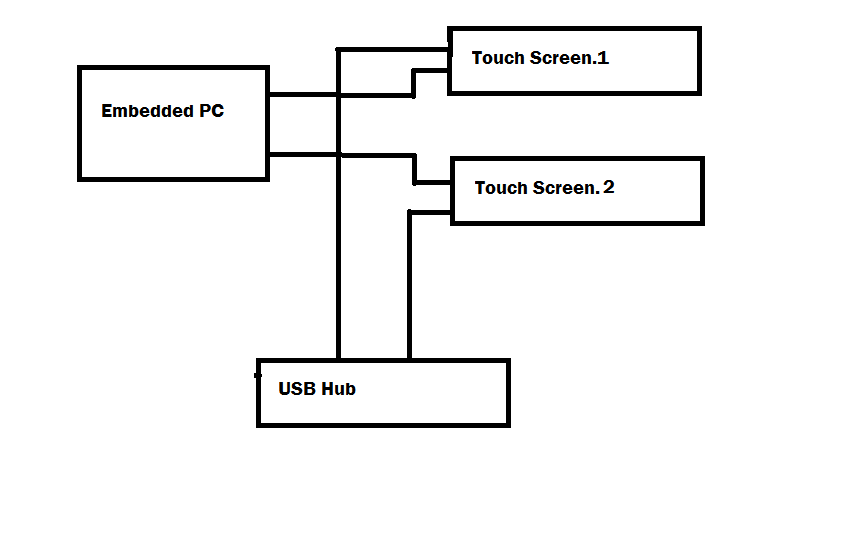
I have to power two touch screens using an embedded PC. The PC can provide 1.5 A maximum through USB ports.

Each screens takes 1 A of current from USB. Thus, there are two USB connectors (in parallel) with each screen.

Overall demand from two screens is 2 A that cannot be handled by the internal power supply of the PC.

The plan is to connect the other USB connector of each screen to an external hub powered up by another power supply.

By doing so, +5 V of the PC will get connected to +5 V of the external hub.

What I am concerned about is the protection in the USB ports of the PC. Can external power be connected to the +5 V output of a USB port directly?
 

I think this scheme will not work. USB port can provide a maximum of 500mA and not 1.5A. And if I understood the question correctly, you want to use the second port of touch screen not as a USB port, but mainly as a power source. No that might not work...
 

I think this scheme will not work. USB port can provide a maximum of 500mA and not 1.5A. And if I understood the question correctly, you want to use the second port of touch screen not as a USB port, but mainly as a power source. No that might not work...

No, there are two screens. Each one with two USB connectors so that 1 A can be drawn through two USB ports.
Thus two screens need to draw 2 A from the PC; 0.5 A more than it's power supply can handle.

Thus I want to connect the second connector of each screen to an external hub with external power supply.

My question is about the compatibility of two power supplies (one PC, another external) in terms of USB devices.
 

Let's try to put this in a drawing... is this what you are trying to do ?


And ... again.. you are saying 1.5A from PC USB Port. Please check that again. As far as I know USB current delivery is not more than 0.5A...
 
  • Like
Reactions: nvd

    nvd

    Points: 2
    Helpful Answer Positive Rating
The PC can provide 1.5 A maximum through USB ports

I mean that this PC can provide 1.5 A through 4 USB ports collectively. If it were a normal PC, I would get 2 A from 4 USB ports.
But this an embedded PC with limited power supply and I do not want to stress it.

Yes, your diagram is correct. It means that I will draw 1 A from 2 USB ports from the PC and draw 1 A from the hub through its 2 ports.

Thus, each screen gets 500 mA from the PC and 500 mA from the hub.

What I am concerned about is the mixing of two different power sources; PC power supply and the hub power supply.
Can USB power be paralleled this way? I am sure that +5 V of the PC power supply will get connected to the +5 V of the hub because
the two USB connectors of the screen are connected parallel to each other.
 

The problem is mainly raised by the bad practice of using more than 0.5 A USB power supply by utilizing a second cable. It's not covered by the USB standard, which allows up to 500 mA optionally for configured devices, not for pure power supply cables, the same with USB fans, lights etc. Nevertheless it works with most computers.

Assuming, your device is also following the said bad practice, you should not power both display USB cables from different sources, because this involves reverse feeding of VBUS, which is an absolute no-no.

You can connect both cables of one or both diisplays to a self powered hub, so they take the full power from the external hub supply.
 
  • Like
Reactions: nvd

    nvd

    Points: 2
    Helpful Answer Positive Rating
FvM covered most of the stuff (As always ) :)

Just to add couple more cents to this.. when we share the power from more than one external sources, it's very essential that we take care of isolation of signals that travel between these sources apart from tieing together all the grounds. In this case you are tying two different US buses. And this will lead to operational issues as well.
 

I was hoping for a diode to prevent reverse feeding but according to FvM, it is missing.

Do you mean USB buses (US buses)?

I think the second USB connector with each screen is only extending the +5 V and GND.
 

Status
Not open for further replies.

Part and Inventory Search

Welcome to EDABoard.com

Sponsor

Back
Top