Continue to Site

Welcome to EDAboard.com

Welcome to our site! EDAboard.com is an international Electronics Discussion Forum focused on EDA software, circuits, schematics, books, theory, papers, asic, pld, 8051, DSP, Network, RF, Analog Design, PCB, Service Manuals... and a whole lot more! To participate you need to register. Registration is free. Click here to register now.

USB connector to and

Status
Not open for further replies.

Rajinder1268

Full Member level 3
Joined
Mar 20, 2021
Messages
162
Helped
1
Reputation
2
Reaction score
4
Trophy points
18
Activity points
1,228
Hi all,
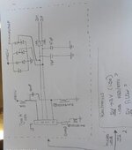
I have attached a schematic of my design. This is part of electronics that will get power from a USB connector from a portable device.
I have connected the USB connector to ground via ferrite beads to reduce EMI. However have seen multiple threads of the connector shield being connected straight to GND, or with a RC parallel connection. I am not sure what is correct. Looking at FTDI hardware guidelines, they have the reference designs connected directly to GND. Can anyone help clear this up?

I am using a 2 layer board. GND on the bottom layer, signals on top and power on top. Should the USB connector be placed with no GND underneath? Finally how do I achieve a ,90ohm differential with a 2 layer board i.e. stack up (assuming 1oz copper). I am not sure how to use Saturn PCB tools. Thanks in advance.
 

Attachments

  • SAVE_20210411_133042.jpg
    SAVE_20210411_133042.jpg
    28.6 KB · Views: 148

Hi,

Many possible solutions.

For shields without acting as signal reference personally often use:
* a high ohmic R to GND in parallel to a low impedance RC

Why:
I like to avoid high DC currents, thus the C. But with the C you risk high frequency resonance, thus a series R (1 ohms .. 10 Ohms)
But now due to the C it is not DC coupled, ESD (permanently introduced by walking on a carpet) may cause hugh voltage across the C.
With a 1MOhms I avoid this.

What I don't like is your ferrite bead at the signal_GND. On a high current pulse between both devices (master, slave) you lose GND reference for the signals. Even if the USB is called differential signalling (thus the signals not urgently need a GND as reference) ... I don't like it

90 Ohms differentisl impedance:
* for short traces you don't need 90 Ohms impedance. Thus I recommend to place connector and IC at close proximity.

Klaus
Thanks for the reply. Why Cant I not connect the usb connector shield straight to 0V? Please could you show the circuit with the RC method that you suggested.
Regarding differential signals, I thought it was necessary to get 90R impedance, hence track length, width and height is necessary?
 

Hi,

Many possible solutions.

For shields without acting as signal reference personally often use:
* a high ohmic R to GND in parallel to a low impedance RC

Why:
I like to avoid high DC currents, thus the C. But with the C you risk high frequency resonance, thus a series R (1 ohms .. 10 Ohms)
But now due to the C it is not DC coupled, ESD (permanently introduced by walking on a carpet) may cause hugh voltage across the C.
With a 1MOhms I avoid this.

What I don't like is your ferrite bead at the signal_GND. On a high current pulse between both devices (master, slave) you lose GND reference for the signals. Even if the USB is called differential signalling (thus the signals not urgently need a GND as reference) ... I don't like it

90 Ohms differentisl impedance:
* for short traces you don't need 90 Ohms impedance. Thus I recommend to place connector and IC at close proximity.

Klaus
I have looked at a FTDI guideline, they use a OR resistor to link the shield and 0V. Could I not bother at all and leave it unconnected i.e. no OV connection?
Thanks in advance.
 

Why Cant I not connect the usb connector shield straight to 0V
Wo said you can't?
Please could you show the circuit with the RC method that you suggested.
As already said:
a high ohmic R to GND in parallel to a low impedance RC.

Regarding differential signals, I thought it was necessary to get 90R impedance, hence track length, width and height is necessary?
What frequency do you calculate with. Then calculate it's wavelength. I doubt your trace on the PCB is that long. I expect it to be much shorter, thus the short traces won't act as 90
Ohm traces.

Klaus
 
Wo said you can't?

As already said:
a high ohmic R to GND in parallel to a low impedance RC.


What frequency do you calculate with. Then calculate it's wavelength. I doubt your trace on the PCB is that long. I expect it to be much shorter, thus the short traces won't act as 90
Ohm traces.

Klaus
Hi, thanks for your help. I am thinking of having the 0R from the shield to GND. However also the RC connected in parallel as DNF. Just a question are the RC Components in parallel? This way I can avoid a re-spin of the board in case I get issues while EMC testing.

My other question is about layout, my micro usb is a smd(pads) and through-hole (shield) type from HIROSE standard receptacle. This would mean the bottom layer will not have any GND directly underneath the USB connector to allow the shields to be connected in the configuration mentioned above. Does that sound correct?
Thanks in advance.
 

Status
Not open for further replies.

Similar threads

Part and Inventory Search

Welcome to EDABoard.com

Sponsor

Back
Top