studystudystudy
Member level 1
i attached a file. Need Pro in power electronic help me explain and analysis the circuit diagram.
this is my first design energy harvesting circuity. but teacher told me have some error, i spend a lot of time in searching the mistake i made. please help me to figure it out!

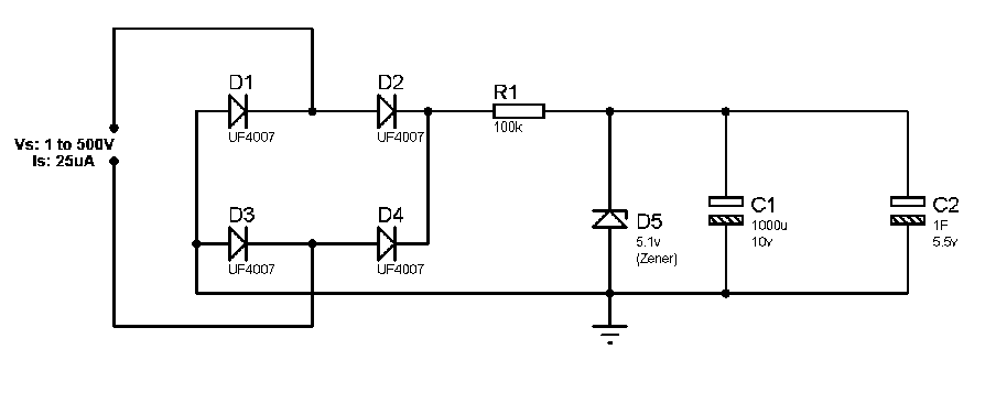
The voltage source is unstable can be ranging from 1 to 1000V
Input current is very small - about 25uA
1. C1 used to filter the DC voltage, but the value use is inappropriate. why? 1000uF with 10V
2. Zener diode connected series with diferrent polarity. used to regulated the voltage so that protect MemoryCap 5V? the Zener diode place in wrong way! why?
3. UF4007 is a ultra fast recovery rectifier. is it already rectifier? mean no need four UF4007 to make a rectifier?
These few question make me headache!!! your help deeply appreciated!! thank you thank you
this is my first design energy harvesting circuity. but teacher told me have some error, i spend a lot of time in searching the mistake i made. please help me to figure it out!

The voltage source is unstable can be ranging from 1 to 1000V
Input current is very small - about 25uA
1. C1 used to filter the DC voltage, but the value use is inappropriate. why? 1000uF with 10V
2. Zener diode connected series with diferrent polarity. used to regulated the voltage so that protect MemoryCap 5V? the Zener diode place in wrong way! why?
3. UF4007 is a ultra fast recovery rectifier. is it already rectifier? mean no need four UF4007 to make a rectifier?
These few question make me headache!!! your help deeply appreciated!! thank you thank you
Last edited: