nikhilsigma
Full Member level 2

- Joined
- Jun 19, 2010
- Messages
- 142
- Helped
- 17
- Reputation
- 34
- Reaction score
- 16
- Trophy points
- 1,298
- Location
- Delhi, India
- Activity points
- 2,584
Hi,
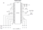
I am trying to make a precise voltmeter(upto 1mV) using a 16bit ADC [ ADS7825 : https://www.ti.com/product/ads7825 ] and a pic micro. Which I will calibrate with an bench multimeter in my lab. I have interfaced the ADC in parallel mode. And I am getting the output almost as desired.. I have made the circuit on the breadboard, and it might be producing some noise(i am not sure about it). I am using channel zero as input and all other channels are grounded. Also since the circuit is built on one breadboard, the analog and digital grounds are also same.
But the problem is that the output of the circuit is not stable. I am getting a variation of about 200mV !!! :-?
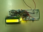
Below is the pic and video of my circuit showing output on LCD. 1st line on LCD shows the voltage measured and 2nd line shows the 16bit binary data received from the ADC. In video the analog input is connected to +5V supply. which have a large 470uF capacitor to ground.

I don't know whats the problem, PLEASE HELP...
I am trying to make a precise voltmeter(upto 1mV) using a 16bit ADC [ ADS7825 : https://www.ti.com/product/ads7825 ] and a pic micro. Which I will calibrate with an bench multimeter in my lab. I have interfaced the ADC in parallel mode. And I am getting the output almost as desired.. I have made the circuit on the breadboard, and it might be producing some noise(i am not sure about it). I am using channel zero as input and all other channels are grounded. Also since the circuit is built on one breadboard, the analog and digital grounds are also same.
But the problem is that the output of the circuit is not stable. I am getting a variation of about 200mV !!! :-?
Below is the pic and video of my circuit showing output on LCD. 1st line on LCD shows the voltage measured and 2nd line shows the 16bit binary data received from the ADC. In video the analog input is connected to +5V supply. which have a large 470uF capacitor to ground.

I don't know whats the problem, PLEASE HELP...


