Continue to Site

Welcome to EDAboard.com

Welcome to our site! EDAboard.com is an international Electronics Discussion Forum focused on EDA software, circuits, schematics, books, theory, papers, asic, pld, 8051, DSP, Network, RF, Analog Design, PCB, Service Manuals... and a whole lot more! To participate you need to register. Registration is free. Click here to register now.

[SOLVED] Understanding Crystal Oscillator

Status
Not open for further replies.

fishcake

Newbie level 4
Joined
Nov 4, 2012
Messages
6
Helped
0
Reputation
0
Reaction score
0
Trophy points
1,281
Activity points
1,345
First of all, let me state that I have very little understanding of electronics, as I just started self-learning not too long ago. So, I thought that it will be a good way to learn electronics by working on fun projects. Thus, I have decided to make a digital clock using a crystal oscillator.

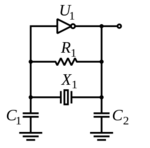
Well, at first I thought I could simply use the crystal to get some oscillation, but I later learned that I need to have some sort of circuit comprised of (2?) capacitors and resistors to actually get an oscillation (schematic obtained from this site), like so:

schematic.jpg

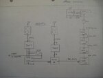
Here's another crystal oscillator circuit (from this site), which is also made to drive a digital clock:
IMG_0564.JPG

As far as I can tell, both of these circuits are the same. So, I guess there must be some reasons as to why it must be like that. Here are my questions:
  1. What is the purpose of the 2 capacitors?
  2. What is the purpose of the resistors? And why are there 2 really high resistors connected in series at the top? What would happen if I were to replace these 2 resistors with a lower value, like around 100K ohms (because I currently don't have resistors with such big values :sad:)?
  3. Why are these components needed to be connected in this way (parallel)?
  4. Why are there 2 outputs from the oscillator circuit (connected to the 10th and 11th pin)?
  5. I have read somewhere about this term called "load capacitance". What does it mean? And how should I know the load capacitance of my crystal if the manufacturer/retailer doesn't provide it (**broken link removed** is what I have)?

Sorry if this is a duplicate question. But to be frank, I actually searched this forum first. It's just that none of the threads I found actually helped me in understanding a crystal oscillator circuit.
 
Last edited:
First of all, let me state that I have very little understanding of electronics, as I just started self-learning not too long ago. So, I thought that it will be a good way to learn electronics by working on fun projects. Thus, I have decided to make a digital clock using a crystal oscillator.
.

Are you really convinced that is the good choice - as a beginner with "very little" understanding of electronics - to start with the circuits as shown in your post?
For my opinion, instead you should start with simple amplifier circuits - either BJT or opamp based or something similar.
But - it`s your choice.

No, I'm not convinced I could understand it that easily. I already spent a few hours searching and reading articles about crystal oscillator circuit, hoping something will "click" in my brain, but it didn't happen. :oops: I didn't know it's considered a difficult circuit, because it looks so simple! Anyway, thanks for the input. I'll probably should start with a simpler circuits.
 

Wanna have fun? Go on with digital electronics: logic gates (AND, OR, NOT ect), switches, diodes, leds, resistors... maybe even registers (PIPO, PISO, SIPO, SISO). And then try adding capacitors (look for schematics online) to make the leds "breathe" (slowly fading in and out light). They're a good way to approach electronics form the newbie side.
Starting with transistors, amplifiers and oscillators at first it's not really a good idea, you'd better have some basics first :)
As for some real analog electronics I'd suggest giving a look at filters, but this may require some knowledge about signals and how filters "filter" them. But it's pretty much an easy job diggin with some random RC filters, so go on! ;)

oh, almost forgot... if you really think you're able to get it about crystal oscillators.. here you are:
https://www.electronics-tutorials.ws/oscillator/crystal.html

Seeyah ;)

Thanks for the input. I really should understand the basics first.

The oscillator used is called a pierce oscillator. I think the wiki page explains it very well. Here's the link for your convenience.

https://en.wikipedia.org/wiki/Pierce_oscillator

View attachment 83318

Didn't know it has a name. Thanks! :)
 

Status
Not open for further replies.

Similar threads

Part and Inventory Search

Welcome to EDABoard.com

Sponsor

Back
Top