Gupsh
Junior Member level 2


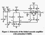
Here for the above circuit the following explaination is given:
Let us assume during the fabrication, the W/L ratio or the
threshold voltage of transistor MI2 is changed such that
the biasing voltage v b z is increased from its designed
value. This will result in corresponding increased current
in active load transistors (M3 and M4). Therefore, the
output voltage of the first stage, as well as the output
voltage of the second stage is lowered. These voltage
variations are-detected by the CMFB mechanisms and
the body voltage of M11 is reduced. This, in turn,
increases the tail current and causes the output voltages
{WO]+V, al-), and (Vo+, Vi)} to rise. This way the
feedback compensates the perturbations Of Vb2.
But I am really not able to understand how by output voltage values are getting lowered by increasing the load current in M3 and M4. Please help!

