ArticCynda
Advanced Member level 1

- Joined
- May 8, 2013
- Messages
- 439
- Helped
- 82
- Reputation
- 164
- Reaction score
- 81
- Trophy points
- 1,308
- Activity points
- 4,238
Hi guys,
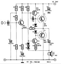
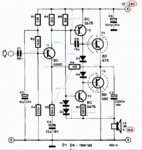
I've found an amplifier design online and built it, and it produces a nice sound quality from my laptop line out! I'm a newbie in transistor amplifiers however, and now I'm trying to understand how the circuit works. I've figured out the following so far:
- R1, R2 and C3 make a low pass RC filter to supply a clean base bias for T1
- R1, R2 and R3 divide the supply voltage to generate a bias voltage for T1
- R5 generates negative feedback to control the AC amplification of T1
- C1 couples the input signal into the preamp around T1
- T3, R7, R8, D1 and D2 make a current source of around 5.5 mA
- T4 and T5 are configured as push-pull power stage, and D3/D4 eliminates distortion due to T4/T5 Vbe offset
- C2 eliminates DC through the speaker
- C8 reduces ripple on the power supply
Now the questions:
- what is R6 for (I assume some sort of feedback)?
- what is C4 for?
- how does the second stage (T2) use the current source exactly?
Can someone hint on how to "calculate" this circuit? For example, how to find the DC emitter voltage of T1, or the base voltage of T4? An example would be awesome!
Thanks in advance!


