Continue to Site

Welcome to EDAboard.com

Welcome to our site! EDAboard.com is an international Electronics Discussion Forum focused on EDA software, circuits, schematics, books, theory, papers, asic, pld, 8051, DSP, Network, RF, Analog Design, PCB, Service Manuals... and a whole lot more! To participate you need to register. Registration is free. Click here to register now.

[SOLVED] ULN2803 Interface

Status
Not open for further replies.

venkates2218

Full Member level 6
Joined
Sep 30, 2016
Messages
354
Helped
1
Reputation
2
Reaction score
1
Trophy points
1,298
Activity points
4,306
Hai,
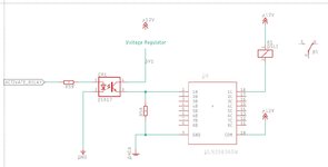
There are two power supplies +5VDC and +12VDC.
+5VDC is given only to MCU and other ICs.Relays are operated by seperate +12VDC.Both power supply having separate GND.
I'm using ULN2803 to operate relays.
My doubt is shall we connect the ULN2803 directly to MCU through resistor to driver relay or shall we use an optocoupler between MCU and ULN2803 to drive relays?
 

Hi,

From my perspective there is no need for seperated GNDs.
I'd connect them.

I see no need for resistors either.

If you see reasons for isolated GNDs and resistors, so tell us your idea. A sketch could be very helpful.

Klaus
 

Hi,

Relays are operated by seperate +12VDC

I assume you are using the 12 V to close the relays.

By using a GPIO pin of the MCU to close the relay, a base voltage is applied at the ULN2803's darlington transistor. So there is current flowing from the base to the emitter as well as a current through the biasing network to the GND (see Functional Block Diagram at page 9 of the DS).

By closing the relay, a current is flowing from collector to emitter towards GND. So the 5 V as well as the 12 V are sharing the same GND connection at the emitter (GND pin of the ULN2803). I do not see how you are able to physically seperate this two GNDs.

Maybe I missunderstood you. A system sketch might be helpful to solve any doubts.

BR
 

No need for resistor, its already there. And effects a pulldown when CPU is tristated to keep
all outputs off when it starts up, if your CPU makes all GPIO inputs or outputs in tristate on
startup.


fbd_slrs049h.gif
\

Regards, Dana
 

This is what i'm think.I dono where it technically correct.All your advise need.
 

Attachments

  • relay.jpg
    relay.jpg
    83 KB · Views: 1,433

A question to consider is, what impact does toggling a
couple of hundred mA into local ground do to your
MCU and any sensitive stuff associated with it. You might
prefer a "star ground" scheme where the relay return
current is routed separately to the prime ground point
of the power connector.

Digital boards don't necessarily have great ground
planes or ground net robustness. It might at least want
some care where you place the relay drivers relative to
power and ground inlet; keeping current loops small
in area is good practice.
 

Hi,

You still don't give any information why you need separate GNDs. I still see no need for it.

Your solution may work.
Issues:
* a lot off effort and cost for the optocouplers.
* you don't need R58
* I recommend to add a bulk capacitor for 12V
* I recommend to add a ceramics capacitor at COM of the ULNxxx

Klaus
 

Your schematic does it like many of the 'relay' boards you can buy on the internet but there is absolutely no advantage at all in using an opto-coupler if the grounds are connected anyway. Just remove R58 and R59 then connect 'ACTIVATE_RELAY' directly to pin 1 of the ULN2803.

The ULN is nothing more than an array of transistors with built in input resistors and clamp diodes, if you only have one relay to drive it is easier to use a single discrete transistor.

A word of caution: The ULN2803's input resistors assume 5V TTL levels are driving it, if your MCU runs from 3.3V you should check the drive voltage is sufficient, you might find it easier to use an NPN transistor or logic level MOSFET instead.

Brian.
 

On state input -

1641039252593.png


1641039307951.png


If you are running 3.3V MCU then look at their GPIO graph of source current to
confirm you can get enough to turn on part. Note if your CPU has GPIO that are
challenged to supply enough source current to meet the need on state Vin do not
add pullups as this would have relays turn on during initial power up when CPU
does not have well defined controlled GPIO state, and the fact most modern CPUs
either tri state their GPIO on power up or select their mode as inputs, once in controlled
operating range for their Vdd. Also those graphs in many datasheets are typical, not
worst case, so thats another consideration.

Note there is graph of needed input current, looks like 1/2 mA will sat the Darlington.


What CPU are you using ? What is relay coil current requirements ? What is CPU supply V ?

There are some octal MOSFET drivers out there -


Even a part controlled via SPI, in case you are running out of pins on CPU....


Regards, Dana.
 
Last edited:

Status
Not open for further replies.

Similar threads

Part and Inventory Search

Welcome to EDABoard.com

Sponsor

Back
Top