Continue to Site

Welcome to EDAboard.com

Welcome to our site! EDAboard.com is an international Electronics Discussion Forum focused on EDA software, circuits, schematics, books, theory, papers, asic, pld, 8051, DSP, Network, RF, Analog Design, PCB, Service Manuals... and a whole lot more! To participate you need to register. Registration is free. Click here to register now.

UC3844 Current sense problem

Status
Not open for further replies.

baby_1

Advanced Member level 1
Joined
Dec 3, 2010
Messages
415
Helped
1
Reputation
2
Reaction score
1
Trophy points
1,298
Visit site
Activity points
4,277
Hello
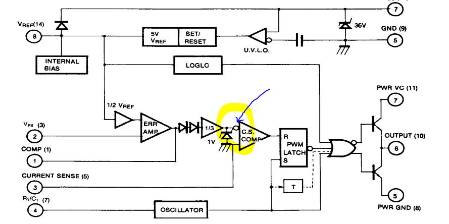
Here as you see the internal Uc3844 block diagram , I have a question about current sense comparator.
7375291400_1405072678.jpg

if we assume the" C.S Comp" section is an op-amp what does the negative buffer pin do?
(it can reverse the zener voltage or not? if yes, it convert to zero or other values?)

thanks
 

Thanks for your response.
could you tell me if we set the "COMP" pin to ground what is "C.S Comp" section output?(and assume the current sense pin's voltage is approximately .5 volt) (it can't get negative value now what does it do?)
 

As I test when I inject zero volt to "COMP" pin it shutdown PWM section.could you tell me about it(how it works?) on the internal circuit of uc3844?
Thanks
 

if u make com 0 u make non inverting terminal high so at output u get a 1. so when s=1 output qbar is 0 and s=0 output qbar =1 leaving at 50% duty cycle so no pwm ........................
 
  • Like
Reactions: baby_1

    baby_1

    Points: 2
    Helpful Answer Positive Rating
Hello
Here as you see the internal Uc3844 block diagram , I have a question about current sense comparator.

if we assume the" C.S Comp" section is an op-amp what does the negative buffer pin do?
(it can reverse the zener voltage or not? if yes, it convert to zero or other values?)

thanks
Hi
Do not try to analyze it's internally circuit because manufacturers won't publish it's real circuit diagram . a person which was analog IC designer noticed me about this issue .
you are not going to be an IC designer am i right ? so just learn how to use it . if the voltage of pin 3 reaches 1 volt thus the IC will shut down the PWM .
That's all and simple .

Good luck
Goldsmith
 
  • Like
Reactions: baby_1

    baby_1

    Points: 2
    Helpful Answer Positive Rating
Status
Not open for further replies.

Similar threads

Part and Inventory Search

Welcome to EDABoard.com

Sponsor

Back
Top