kanmaedexandzelbladex
Member level 1

- Joined
- Jul 20, 2013
- Messages
- 35
- Helped
- 1
- Reputation
- 2
- Reaction score
- 1
- Trophy points
- 8
- Location
- Philippines
- Activity points
- 479
Hi all, I am trying to make a 45V boost converter with a max output of 90W. My input range is from 11V to 19V. I already have the hardware implementation of the whole converter and have tested it. I have here some waveforms of inductor current (blue) together with Vds of mosfet switch (yellow). As can be seen, the subharmonic oscillations start occurring at 0.6A load and higher. Below 0.6A load, the waveforms are fine. My input voltage is around 15V at the time the waveforms where taken.
I have thought about the following things and would like to hear some opinion of them:
1.) I've had an observation with slope compensation in that when I try to increase the value of the slope being added to the current sense signal, I am able to reach higher loads without getting into subharmonic oscillation. The problem is that, whenever I increase it more and more, the output voltage starts to drop while removing the subharmonic oscillation! I am sensing that this must be due to the fact that the added slope is what dominates the net current sense signal and the current loop does not anymore see the effects of the variation of the actual current loop. I have verified this with a simulator and it shows exactly the same thing. The output voltage regulates up to higher loads, but at a smaller value than intended. I have heard that increasing the added slope makes the control more like voltage-mode and hence its disadvantages are acquired, but voltage-mode control doesn't mean poor steady-state regulation. Do you have explanations on this?
2.) Following number 1, so at higher slopes being added, there is a trade off between current loop stability and voltage regulation? Because my plan of action would be to increase and increase my added slope until such time that there is no current loop stability up to full load but it might come to a point wherein I could no longer maintain regulation when opting for more stability. What can I do in such a case?
3.) Will my voltage loop compensation (I used a Type II compensator) affect my current loop stability? Is the slope compensation dependent also on my voltage loop compensator?
4.) Does switching frequency have any effect on slope compensation and subharmonic oscillations?
5.) My simulations show that when subharmonic oscillations occur due to lack of slope compensation, the output voltage does not drop, it only has ugly ripple. In my actual implementation, whenever the subharmonic oscillation strikes (from 0.6A onwards), the output voltage drops! Are there any explanations to the inconsistency between the simulation and the actual implementation?
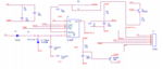
For more info, my control section implementation is also attached here. Some explanations:
*The control section is implemented as a daughterboard for the power section with J1 being the connector.
*Vin is connected to the input of the boost converter, Isense is attached to a 5 milli Ohm sense resistor in series with the source of the switching mosfet, Vfb is attached to a resistive divider that samples from the output voltage of the boost converter, COMP pin is floating - it is not attached to any point in the power section (as of now), Switch Drive is the MOSFET switch gate drive
I also have another question.
My implementation of the slope compensation is that Q1 common collector samples from RTCT (which determines the frequency and duty cycle clamp of the converter) and passes it to the resistive divider R5 and R2 thereby adding slope. The problem is that if I try to decrease R5 (to increase slope being added), it loads the RTCT pin which changes the switching frequency of the converter. What are my options for this? I am planning to try and use a darlington pair for Q1 to avoid loading effect, will this work? What else might work?
Thank You
I have thought about the following things and would like to hear some opinion of them:
1.) I've had an observation with slope compensation in that when I try to increase the value of the slope being added to the current sense signal, I am able to reach higher loads without getting into subharmonic oscillation. The problem is that, whenever I increase it more and more, the output voltage starts to drop while removing the subharmonic oscillation! I am sensing that this must be due to the fact that the added slope is what dominates the net current sense signal and the current loop does not anymore see the effects of the variation of the actual current loop. I have verified this with a simulator and it shows exactly the same thing. The output voltage regulates up to higher loads, but at a smaller value than intended. I have heard that increasing the added slope makes the control more like voltage-mode and hence its disadvantages are acquired, but voltage-mode control doesn't mean poor steady-state regulation. Do you have explanations on this?
2.) Following number 1, so at higher slopes being added, there is a trade off between current loop stability and voltage regulation? Because my plan of action would be to increase and increase my added slope until such time that there is no current loop stability up to full load but it might come to a point wherein I could no longer maintain regulation when opting for more stability. What can I do in such a case?
3.) Will my voltage loop compensation (I used a Type II compensator) affect my current loop stability? Is the slope compensation dependent also on my voltage loop compensator?
4.) Does switching frequency have any effect on slope compensation and subharmonic oscillations?
5.) My simulations show that when subharmonic oscillations occur due to lack of slope compensation, the output voltage does not drop, it only has ugly ripple. In my actual implementation, whenever the subharmonic oscillation strikes (from 0.6A onwards), the output voltage drops! Are there any explanations to the inconsistency between the simulation and the actual implementation?
For more info, my control section implementation is also attached here. Some explanations:
*The control section is implemented as a daughterboard for the power section with J1 being the connector.
*Vin is connected to the input of the boost converter, Isense is attached to a 5 milli Ohm sense resistor in series with the source of the switching mosfet, Vfb is attached to a resistive divider that samples from the output voltage of the boost converter, COMP pin is floating - it is not attached to any point in the power section (as of now), Switch Drive is the MOSFET switch gate drive
I also have another question.
My implementation of the slope compensation is that Q1 common collector samples from RTCT (which determines the frequency and duty cycle clamp of the converter) and passes it to the resistive divider R5 and R2 thereby adding slope. The problem is that if I try to decrease R5 (to increase slope being added), it loads the RTCT pin which changes the switching frequency of the converter. What are my options for this? I am planning to try and use a darlington pair for Q1 to avoid loading effect, will this work? What else might work?
Thank You