Continue to Site

Welcome to EDAboard.com

Welcome to our site! EDAboard.com is an international Electronics Discussion Forum focused on EDA software, circuits, schematics, books, theory, papers, asic, pld, 8051, DSP, Network, RF, Analog Design, PCB, Service Manuals... and a whole lot more! To participate you need to register. Registration is free. Click here to register now.

Two stage op-amp design stability and accuracy

Status
Not open for further replies.

gvardan

Newbie level 6
Joined
Jun 15, 2010
Messages
13
Helped
0
Reputation
0
Reaction score
0
Trophy points
1,281
Location
Canada
Activity points
1,434
Hi,
first of all I'm really sorry for a bad diagram, plus I'm fairly new for analog designs.

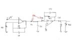
I'm trying to design a instrumentation circuit for a color sensor. In order get the maximum accuracy out of ADC i had to use two stage amplification. I somehow managed to get this circuit, but I'm kind of confused in the filter part I'm using to get rid of the high frequency noises from op amps.

So my concerns are,
After the first stage I'm using a low pass filter, can this resistance from the filter be used as the input impedance for the second stage. do i read the RIN there??

Besides, should i include the Co to the CF2 calculation to compensate the stability of second stage op-amp??

Or is it possible to just have one filter for both op-amps..

Schematic Attached to the thread!

I would really appreciate some help or any good reference.

Thank you.
 

Attachments

  • Diagram.JPG
    Diagram.JPG
    15.9 KB · Views: 146
Last edited:

Hi.

I need to understand the color sensor to understand how you plan to use the circuit.

The first stage will try to maintain voltage over the sencor at 2.5V. So changes in current will cause output swing. The first stage will act like a LS filter, and so will R0/C0 do AND the last stage.
 

What are your dc power sources? Single or double supply?
Be aware that Rin loads the rc lowpss and determines the frequency response.
Why do you expect stability problems for the 2nd opamp?
 

@Prototyp_V1.0
it's a MTCSiCS color sensor, and the diagram shows how I'm using it.
 

@LvW
Thanks for your reply,
It's a dual +/-5 supply, FYI, I'm using that +2.5 offset for two reasons, since its a transmittance the out put of the op-amp will swing between 0 to -5, so I'm making it systematic besides there are some switches involved which I haven't showed here , to compensate the switch current leakages i had to make the op-amp offset to 2.5. And I'm using a high pass filter to avoid any high frequency notices.

Well from my understanding when we choose the C12, though it's depended on the settling time of the op-amp we need to make sure that its higher than the total input capacitance for stability.

It's just a small confusion, my confusion is that will the LP filter's RO,CO be also the input Independence and capacitance for the second op-amp? in that case do i need an RIN??
 

Thank you for this comprehensive information.

Sorry, i had to answer a call while i was replying.

---------- Post added at 16:35 ---------- Previous post was at 16:26 ----------

Does the datasheet says that the sencor need 2.5 volts to operate properly?

Ok, first of all i really appreciate all of your helps, but just calm down, i was going to reply the rest of the information to LvW's reply, because his question made more sense.

Besides my area of question is with the LP filter and op-amps, its more like the theory clarification. Though i understand the need to understand the whole circuit..

By the way i haven't marked a 2.5 supply for the sensor, i don't know where you say that 2.5 supply for sensor.. that 2.5v supply is for opamp.. just in case you dint notice PD(photodiode) is the sensor..

---------- Post added at 16:38 ---------- Previous post was at 16:35 ----------

Does the datasheet says that the sencor need 2.5 volts to operate properly?

Well's there's a wide rang of power supply for sensor 0 to 5?? but where do you see that 2.5 supply for sensor ???? PD is the sensor(photo diode).. and FYI I'm using 4.5V supply for that, but that doesn't have anything to do with the op amp(trans impedance) out put.
 

By the way i haven't marked a 2.5 supply for the sensor, i don't know where you say that 2.5 supply for sensor.
I sait it because I taught that the intention.

Imagine the first opamp stage as a variant of a voltage follower. As it is wired now, the opamp will always attempt to make the voltage at it's negative output being equal to the voltage on the positive terminal.

Because of this, (given the properties of the sensor allows it) the voltage over the sencor will stay 2.5V.
 

.....................
It's just a small confusion, my confusion is that will the LP filter's RO,CO be also the input Independence and capacitance for the second op-amp? in that case do i need an RIN??

Yes, Rin is needed - otherwise, Co has no meaning. But - as mentioned - Rin must be incorporated into the LP design, unless the value of Rin is high if copared with Ro. Best solution: RoCo decoupled from the active filter with a unity-gain-amplifier or cancel RoCo and replace the 1st order activ filter by a second order stage.
 

I sait it because I taught that the intention.

Imagine the first opamp stage as a variant of a voltage follower. As it is wired now, the opamp will always attempt to make the voltage at it's negative output being equal to the voltage on the positive terminal.

Because of this, (given the properties of the sensor allows it) the voltage over the sencor will stay 2.5V.

Your theory is absolutely correct. And it's my bad i didn't have the diagram proper. Because as i said before my area of concern is not on the sensor, i wanted to clear out the filter combination with amps.
But, yea FYI, the photo diode is reverse biased in practical, and how much voltage over is also depend on our supply voltage to the sensor. e.g if we supply with 4v, then as you said the negative input of the op-amp would have 2.5 which is also the positive end of the diode and the other end of diode would have 4V, which will make the voltage over the sensor 4-2.5=1.5V. Hope that helps. I really appreciate your interest in this, thanks man.

---------- Post added at 20:28 ---------- Previous post was at 20:25 ----------

Yes, Rin is needed - otherwise, Co has no meaning. But - as mentioned - Rin must be incorporated into the LP design, unless the value of Rin is high if copared with Ro. Best solution: RoCo decoupled from the active filter with a unity-gain-amplifier or cancel RoCo and replace the 1st order activ filter by a second order stage.

Thanks for your notes LvW, ill look into it.

By the way, are you guys aware of any good reference for dual stage amp design and analysis.
 

Status
Not open for further replies.

Similar threads

Part and Inventory Search

Welcome to EDABoard.com

Sponsor

Back
Top