hmalissa
Junior Member level 2
- Joined
- Apr 21, 2010
- Messages
- 23
- Helped
- 0
- Reputation
- 0
- Reaction score
- 0
- Trophy points
- 1,281
- Location
- New Jersey
- Activity points
- 1,492
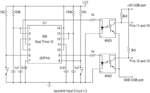
I need to read a TTL signal on the PC through the parallel port, and I'm thinking of using one of the status pins (10, 11, 12, 13, or 15).
In particular, the signal is the "output" pin of a LM555, and according to the specifications, it is around 3.3V when high when the LM555 supply voltage is 5V.
Can I connect the the LM555 output directly to pin 10, 11, 12, 13, or 15 of the parallel port? And, if not, what would be the proper way to read the TTL signal through the parallel port?
Thanks a lot.