evios
Junior Member level 1
wattmeter schematic
Watt Meter
Project reference: **broken link removed**
ASM code: **broken link removed**
Schematic: **broken link removed**
My Watt meter:
I am using the schematic as shown above, however there is minor change where I didn’t use any switches (S1, S2, and S3) and the shunt resistor, R15 used is 1 Ω. I’d asked the author of this project, he mentioned I can neglect the rpm input at RB0 pin 6 of PIC16F88. So basically the overall idea is to measure the power dissipated in terms of watt.
After the schematic has been connected, I manage to get this on the LCD screen:
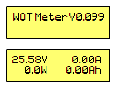
*However, sometimes I may have readings even without connecting any load to it.
Question 1: May I know what cause this?
Then, I tried to connect both the LOAD + and LOAD – together, what I get is:

The maximum value allowed by the author and the project.
All values are constant while the Ah value keeps on increasing. (I think it is because I want to measure watt, so timer is needed here).
There are several questions that I really need to know regarding this project as I am an ASM language numb. I really appreciate your help on this.
1. May I know the overall concept on how this watt meter is built? As I know to get Watt (power), I need to know voltage, current, and resistance. In this project, there are two parts, one on the shunt current (if not mistaken), and the one connected to the PIC16F88 measuring the voltages. So computation on the reading (watt) is done by getting the analog values of both and do the analog to digital (ADC) within the PIC.
2. I see there are changes when load is connecting to the watt meter. Only the voltage reading 25.58V keeps constant on the LCD while other changing. Ah (Ampere hour) is increasing secondly and both the watt (W) and current (A) have the values changes. May I know is the watt and ampere value are being shown simultaneously each time the calculation done instantaneously?
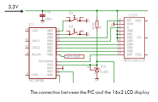
3. Refer to the connection as shown above; there are 4 outputs from the PIC to the LCD. RA4 to DB7, RB1 to DB6, RB2 to DB5, RB3 to DB4. As this watt meter using a 16x2 line LCD, so as I know 2 data buses are corresponding to the characters displayed on the LCD and the other two are used to control the LCD. May I know which two data buses responsible for this? I need these two data buses to connect to the digital IO of my RF module.
4. I am using a 9V battery as the input. Providing the facts of using shunt resistor of 1Ω, I wonder what the range of the load I might use. And I found that for the four data buses, DB7 is the only one with high voltage of 3.8V. May I know what does that mean? Leak?
Well, I had gone through the progress of implementing the hardware until now. So hopefully I can have someone guide me and advice me on my debug progress. I really appreciate your help. Thank You. By the mean time I will also trouble shoot it on my own. Guidance and help are needed. Thanks again.
Watt Meter
Project reference: **broken link removed**
ASM code: **broken link removed**
Schematic: **broken link removed**
My Watt meter:
I am using the schematic as shown above, however there is minor change where I didn’t use any switches (S1, S2, and S3) and the shunt resistor, R15 used is 1 Ω. I’d asked the author of this project, he mentioned I can neglect the rpm input at RB0 pin 6 of PIC16F88. So basically the overall idea is to measure the power dissipated in terms of watt.
After the schematic has been connected, I manage to get this on the LCD screen:
*However, sometimes I may have readings even without connecting any load to it.
Question 1: May I know what cause this?
Then, I tried to connect both the LOAD + and LOAD – together, what I get is:
The maximum value allowed by the author and the project.
All values are constant while the Ah value keeps on increasing. (I think it is because I want to measure watt, so timer is needed here).
There are several questions that I really need to know regarding this project as I am an ASM language numb. I really appreciate your help on this.
1. May I know the overall concept on how this watt meter is built? As I know to get Watt (power), I need to know voltage, current, and resistance. In this project, there are two parts, one on the shunt current (if not mistaken), and the one connected to the PIC16F88 measuring the voltages. So computation on the reading (watt) is done by getting the analog values of both and do the analog to digital (ADC) within the PIC.
2. I see there are changes when load is connecting to the watt meter. Only the voltage reading 25.58V keeps constant on the LCD while other changing. Ah (Ampere hour) is increasing secondly and both the watt (W) and current (A) have the values changes. May I know is the watt and ampere value are being shown simultaneously each time the calculation done instantaneously?
3. Refer to the connection as shown above; there are 4 outputs from the PIC to the LCD. RA4 to DB7, RB1 to DB6, RB2 to DB5, RB3 to DB4. As this watt meter using a 16x2 line LCD, so as I know 2 data buses are corresponding to the characters displayed on the LCD and the other two are used to control the LCD. May I know which two data buses responsible for this? I need these two data buses to connect to the digital IO of my RF module.
4. I am using a 9V battery as the input. Providing the facts of using shunt resistor of 1Ω, I wonder what the range of the load I might use. And I found that for the four data buses, DB7 is the only one with high voltage of 3.8V. May I know what does that mean? Leak?
Well, I had gone through the progress of implementing the hardware until now. So hopefully I can have someone guide me and advice me on my debug progress. I really appreciate your help. Thank You. By the mean time I will also trouble shoot it on my own. Guidance and help are needed. Thanks again.