Continue to Site

Welcome to EDAboard.com

Welcome to our site! EDAboard.com is an international Electronics Discussion Forum focused on EDA software, circuits, schematics, books, theory, papers, asic, pld, 8051, DSP, Network, RF, Analog Design, PCB, Service Manuals... and a whole lot more! To participate you need to register. Registration is free. Click here to register now.

Trouble with fan speed regulator using PIC18f4550

Status
Not open for further replies.

DatsAbk

Member level 3
Member level 3
Joined
Jun 22, 2012
Messages
55
Helped
0
Reputation
0
Reaction score
0
Trophy points
1,286
Visit site
Activity points
1,704
Hello Friends,
I've been trying to make an AC fan regulator that can be controlled electronically using a controller. I have already detected the zero crossing perfectly using 4n35 optocoupler. I've seen the pulses on the digital oscilloscope too. I saw the rectified wave and zero crossing pulses together and they are perfect. I also achieved shifting of the pulses as per the count entered. But when I use the triac circuit attached here, it Capture.JPG works perfect at full speed but doesnt work at lower speeds.

I dont understand where the trouble is. The wave supplied to the fan is perfect at full speed but it get highly distorted at any other speed value.
 

MOC3041 has inbuilt zero crossing detor ckt. it'll trigger the TRIAC when the supply crossing zero (zero volt switching). If u r trying for phase angle contro method u need to use MOC3021.

Ref: http://www.datasheetcatalog.org/datasheet/motorola/MOC3021.pdf

use the ckt on pg no. 4
includes a capacitor which will act as snubber will give better result.
 

But what difference would the change in optocoupler make??

Zero crossing is needed to sychronize the triggering pulses with the AC wave.

But I'm unable to achieve it successfully when trying with fan....:(
 

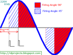
if a opto diac module has inbuilt zero crossing detector it'll trigger TRIAC only when it crosses zero even u give trigger command at any position of the phase ex 90 deg

but if it doesn't have zero crossing detector it'll trigger the TRIAC immediately at the same instant of the LED I/P which u r giving.

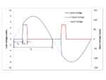
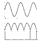
I hope with the following waveform u can understand easily
MOC3021

firing angle.PNG
ACWave.png

MOC3041

sine.gif
MOC3041.JPG


Ref: https://playground.arduino.cc/Main/ACPhaseControl
 

Hello jpganesh,
Thanks a lot for this suggestion. But still I'm confused why MOC3010 failed then???

It doesnt have a zero crossing detector...:(

Also my triac BTA24-600B heats up at just 2A which is highly impractical. I'm using 8.2k resistor at gate terminal
 

MOC3041 has inbuilt zero crossing detor ckt. it'll trigger the TRIAC when the supply crossing zero (zero volt switching). If u r trying for phase angle contro method u need to use MOC3021.

Ref: http://www.datasheetcatalog.org/datasheet/motorola/MOC3021.pdf

use the ckt on pg no. 4
includes a capacitor which will act as snubber will give better result.

8.2K is very high value that's what I think. reduce it to lesser value. have a look at my previous post (quoted here)

try this ckt. I used MOC3021 with BT136. It worked well.

first try with 90 deg firing angle. because if ur zero crossing gives pulse before zerocrossing then ur conroller may trigger at wrong undesired position. so at first try to fire at 90 deg. so that more time gap will be tre. if u get proper result for 90 deg then goahead with different firing angle.

Ohk,Thanks dude. M trying it with MOC3021 now. Will use snubber circuit too and then check heating. What was the value of resistor that you used?

Was there a resistor between gate and A1 terminal or only one resistor between A2 and gate?

A1 is 1st pin of triac, A2 is 2nd and 3rd is gate
 

MOC3021.JPG

this ckt has snubber for optocoupler too (DIAC side).

after successful run I changed R1, R2 and C1 values still it worked fine.
but R values i tried with less than 1K only.

Was there a resistor between gate and A1 terminal or only one resistor between A2 and gate?
no need and I didn't put

A1 is 1st pin of triac, A2 is 2nd and 3rd is gate
for PIN detail refer it's datasheet of the TRIAC which u r using
 

View attachment 89903

this ckt has snubber for optocoupler too (DIAC side).

after successful run I changed R1, R2 and C1 values still it worked fine.
but R values i tried with less than 1K only.


no need and I didn't put


for PIN detail refer it's datasheet of the TRIAC which u r using

Hey give me five dude...:D

I dimmed a bulb finally with just change in optocoupler.Its moc3021. Will look now for the heating problem. Currently i have a small heat sink only. So will try and achieve success somehow....keep helping...:D
 

sure man. happy to help u :smile:

- - - Updated - - -

https://www.edaboard.com/threads/286530/
 

Hey give me five dude...:D

I dimmed a bulb finally with just change in optocoupler.Its moc3021. Will look now for the heating problem. Currently i have a small heat sink only. So will try and achieve success somehow....keep helping...:D

Hey dude,need help once again. I dimmed the fan too easily but the problem is that the fan turns off if I trigger after the first half of positive half cycle of voltage. Seems like it is because of current lag as fan is inductive load.....so I have set 5 steps in the first half of the cycle only. But when the fan is at a slower speed, it makes minor noise as if its connected to an impure sine wave.The sound is like the one that comes when an inverter is connected to the supply.

Please suggest a solution for it
 

Status
Not open for further replies.

Part and Inventory Search

Welcome to EDABoard.com

Sponsor

Back
Top