Continue to Site

Welcome to EDAboard.com

Welcome to our site! EDAboard.com is an international Electronics Discussion Forum focused on EDA software, circuits, schematics, books, theory, papers, asic, pld, 8051, DSP, Network, RF, Analog Design, PCB, Service Manuals... and a whole lot more! To participate you need to register. Registration is free. Click here to register now.

transistor understanding difficulties

Status
Not open for further replies.

libyantiger

Member level 5
Joined
Aug 10, 2016
Messages
90
Helped
0
Reputation
0
Reaction score
3
Trophy points
1,288
Activity points
2,269
hello

what i know

it is well understood that a transistor amplifeir is firstly done by fixing the transistor some where in the active region where basically the transistor is

never full on nor fully off

and in between transistor which have some current flow some voltgae across e and c is ready for amplifications usually when vcc is 10vdcs ic when transistor is fully on is 1 amp


the best point is 0.5 amps and 5vdc the word "fixing transistor " means tweaking value of resistor some how to put the transistor in this active region

when the ac signal applied it "ride " on dc lever cause change in base voltage which change base current which change collector current hugly which is what amp is really is

what i dont know


my

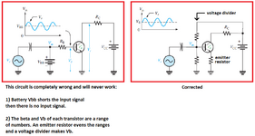
first question how on earh in the figure this ac is on top of the dc it is picture taken form the floyd book very respectable book and to my maximum torture is that the autor have utilized " my theory " of ac source on the dc source in some examples but then back to use the less obvious method of using the ac source in parralell wiith dc if some one can ezplain how that can be called an amplifications i never connect to dc or ac source in parrallell and willl never try or calculate what happen after that


my


second question

if all text book can utilise ,my "theory " of putting the ac signal source on the dc evern the most difficult method of basing can understood pls check and verify my understanding
of the common base baising

in common base the emiitter resistor "govern" the ie it is what determine the ie giving by kerchov law across base emitter and the vcc -5 volt the ie have been decided
any ac voltage acrosss the the input will increase ie or decrease it >>>>>ic is almost equall to ie so no current amplification will result however

voltage amplification can happen since ic and ie almost equal then if large out put resistor will reustl in large voltage swing across it which is what common base is used not current amp but voltage amp
in depth.png


thanks i believe i have flaw in my understanding but i dont know where
 
Last edited:

I'm having a very difficult time understanding what you've written, my apologies I assume English is not your first language.

For your first question, if I understand, you're asking how a DC and AC source can be added like the book shows. That happens because of the capacitor. Capacitors block DC and allow AC through. The battery charges the capacitor so the right side of the capacitor is the battery voltage, and the left side is 0V. The AC voltage then wiggles up and down, which wiggles the right side of the capacitor.

For your second question, the equation for common base is the same as common emitter, except the gain is positive instead of negative. Remember that the common emitter inverts the signal, common base does not. Not sure what you mean by "not current amp but voltage amp"??
my main question is that in the figur there is an ac source on the dc source that is


nice intuitive and very understandable


but there is ac source that is seems in parallel on the dc that is not nice not intuitive
and not understandable


i think now my questions is understandable
--- Updated ---

the green mark on the picture means normal ac on dc source that is understanable


red marks on picture means that the ac seems to me not "riding above " or "setting on " the dc which to me is abnormal


my question is to explain to me how that is normal for ac source that is not riding on the dc source

is good and normal


to me red one amplifications canot happpen

to the green picture amplification can happen and it is sound good and normal configuration
 
Last edited:

The circuit from the book is completely wrong.
AC fed through the input capacitor to the base of the transistor is supposed to modulate (ride on) the DC base bias voltage (the AC modulates the DC). But the battery Vbb voltage is connected directly to the base and it is impossible to modulate the battery voltage. A voltage divider is needed to set the DC base voltage. The battery Vbb is not needed because the voltage divider can use the Vcc voltage.

Since the Vb of a transistor and its beta are a range of numbers then a series emitter resistor is used to even the numbers. If more amplification is needed then the added emitter resistor can be paralleled with a capacitor.

Why do you need the massive current of 0.5A in the transistor? 0.5A is higher than the max allowed current in most little transistors and causes the transistor to heat with 5V x 0.5A= 2.5W all the time, even when there is no input signal. 2.5W will burn all little transistors.
 

Attachments

  • transistor amplifier.png
    transistor amplifier.png
    44.9 KB · Views: 92
The circuit from the book is completely wrong.
AC fed through the input capacitor to the base of the transistor is supposed to modulate (ride on) the DC base bias voltage (the AC modulates the DC). But the battery Vbb voltage is connected directly to the base and it is impossible to modulate the battery voltage. A voltage divider is needed to set the DC base voltage. The battery Vbb is not needed because the voltage divider can use the Vcc voltage.

Since the Vb of a transistor and its beta are a range of numbers then a series emitter resistor is used to even the numbers. If more amplification is needed then the added emitter resistor can be paralleled with a capacitor.

Why do you need the massive current of 0.5A in the transistor? 0.5A is higher than the max allowed current in most little transistors and causes the transistor to heat with 5V x 0.5A= 2.5W all the time, even when there is no input signal. 2.5W will burn all little transistors.
my question is in the picture
transistor amplifier (1).png
 

I believe that the Author has used VBB for illustration only but this can be open to misinterpretation.
As said, VBB will make short circuit the Base.
 

My base bias voltage divider resistors have high enough values then the input signal through the capacitor can easily modulate the DC base bias voltage with the AC input signal. Then the base DC bias has the signal AC riding on it.
The capacitor prevents (blocks) the DC of the signal source from changing the important DC bias voltage at the base of the transistor. Therefore the capacitor must never be shorted but it has a very low reactance impedance (passes AC) at the audio frequencies.
 

That illustrations are unreliable and want checking,
is perhaps the most important lesson. The world
is full of error and obfuscation.
 

thanks i believe i have flaw in my understanding but i dont know where
It is the capacitor.

Let me try to explain in simple words.

Consider two voltage sources. Can you connect them in parallel? The answer is NO!

Why? unless they are having the same voltage exactly, the fellow with the slightly higher voltage will try to push some current into the other voltage source. As the ideal voltage sources have zero resistance, this mean you will push infinite current.

So we rarely connect batteries in parallel because if one of them is having a higher voltage (even slightly), that will drive some current into the other cell with a lower voltage. But real batteries cannot supply infinite current and their voltages drop when they deliver a current.

Now you connect two voltage sources with a capacitor. A capacitor can pass only a transient current. The two ends of the capacitor will have two different potentials but that is ok. The capacitor gets charged but no current flows in the steady state. An ideal capacitor has infinite resistance at DC.

Now consider one of the voltage sources (say the left one) is AC. Capacitor has finite impedance at AC frequency and some current will flow. But the right side voltage source is having a zero impedance and the voltage on the right side will NOT change. As if you have connected this end to the ground.

Real voltage sources have some resistance and the voltage will change a little. That is the reason you can put batteries in parallel in real life because they have some finite (small but non-zero) resistance. And that is also the reason you should not mix old and new cells. And you should not parallel different types of cells. But when you put cells in parallel you increase the current capacity. When you put them in series, you increase the voltage capacity.

I hope I am clear.
 

well let me brief my question again


looking at this new picture that i uploaded in the red square marked section


it seems to me that the 2 sources are not riding on each other (despite the fact that most text books say that they are ride on each other how ever i cant see how
and i draw my scope expectation


looking again in green marked section


well thos are what the word ride on each other is..... not commonly used in text books but to me it is sound correct and i draw my scope expectation


i am not to oppose text books who is me to confront the mighty floyd or seddra etc etc


but to me to my understaznding that is not sound i need some one to correct me not to correct the text books

note


in red picture i assummed that the 5vdc bais is at node between the base voltage didvder so that is where the 5vdc come from


ofcourse you will see 5vdc in my scope draw so now it is all clear from where this 5vdc come from
2222.png

thanjks all
--- Updated ---


--- Updated ---
 
Last edited:

The base of a transistor and the two resistors biasing it at 5V are a fairly high resistance. The coupling capacitor has a fairly low reactance then it can easily modulate the 5V up and down, not just the positive peaks.
 

well let me brief my question again
automerge]1628029257[/automerge]


--- Updated ---


looking at this new picture that i uploaded in the red square marked section


it seems to me that the 2 sources are not riding on each other (despite the fact that most text books say that they are ride on each other how ever i cant see how
and i draw my scope expectation


looking again in green marked section


well thos are what the word ride on each other is..... not commonly used in text books but to me it is sound correct and i draw my scope expectation


i am not to oppose text books who is me to confront the mighty floyd or seddra etc etc


but to me to my understaznding that is not sound i need some one to correct me not to correct the text books

note


in red picture i assummed that the 5vdc bais is at node between the base voltage didvder so that is where the 5vdc come from


ofcourse you will see 5vdc in my scope draw so now it is all clear from where this 5vdc come from
thanjks all
I do not think you are having a problem with transistor operation and principles. I think your basic problem is with simple concepts of current and voltage. are you familiar with Kirchoff's laws, Thevenin and Nortons theorems? They help you clear the confusion.

You can forget about the transistor for the time being and focus on the voltages at different points of the circuit.

Then draw the waveforms at different points.

Because I want to know what is the exact concept you are not able to grasp.
 

Status
Not open for further replies.

Similar threads

Part and Inventory Search

Welcome to EDABoard.com

Sponsor

Back
Top