Continue to Site

Welcome to EDAboard.com

Welcome to our site! EDAboard.com is an international Electronics Discussion Forum focused on EDA software, circuits, schematics, books, theory, papers, asic, pld, 8051, DSP, Network, RF, Analog Design, PCB, Service Manuals... and a whole lot more! To participate you need to register. Registration is free. Click here to register now.

Transistor As Switch Without Any Voltage Drop ?

Status
Not open for further replies.

asking

Full Member level 5
Joined
Sep 21, 2010
Messages
279
Helped
6
Reputation
12
Reaction score
6
Trophy points
1,298
Activity points
3,377
Hello,

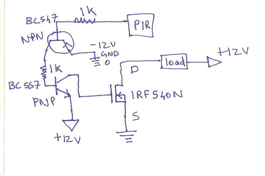
I have been trying to use Transistor in place of Relay (as relay causes noise) but i m afraid...every transistor has PN junction voltage drop. Please can you gimme idea/design how to use transistor as pure switch means no voltage loss.....

thanks...
 

Use a MOSFET. It has a drain-to-source resistance when conducting (Rdson) and at low voltages, the voltage drop should be very small. You can get MOSFETs with very very small Rdson, which will result in near-zero voltage drop. N-channel MOSFETs tend to have lower Rdson than P-channel MOSFETs for similarly rated devices.

Hope this helps.
Tahmid.
 

Yes its DC Current Maximum Load is 5-7AMP @ 12-14Volt. Please suggest me some Logic Level Mosfet's...

- - - Updated - - -

Yes its DC Current Maximum Load is 5-7AMP @ 12-14Volt. Please suggest me some Logic Level Mosfet's...
 

Yes its DC Current Maximum Load is 5-7AMP @ 12-14Volt. Please suggest me some Logic Level Mosfet's...

- - - Updated - - -

Yes its DC Current Maximum Load is 5-7AMP @ 12-14Volt. Please suggest me some Logic Level Mosfet's...

go to either digikey or mouser website, search MOSFET, then device parameters you would look for say Vgs breakdown ~10-12V, choose RDSon low value,
choose continuous drain current. Prices vary, generally, lower RDSon => more $
you need to check with the datasheet, how "on" it is at 5V - aka logic level - there is usually a graph Vgs and RDSon.
You might then find the same part numbers at your preferred supplier.


This is the MOSFET Driver circuit i have designed. Please comment is is true ? Thanks. My PIR output is 3.3volt. When i connect directly with IRF540N it works but my Display (load) is little dim. Means directly using 3.3v its not fully on.
 

sorry the transistor symbols are wrong...else i think everything is fine... please do comment...will it work.. i want to use IRF540 as Pure switch as its RDson is very low..
 

Please post you circuit with the proper transistors symbols since your posted circuit will not work.

What is the output voltage from the PIR sensor?

The IRF540 requires a gate-source (Vgs) voltage of +10V to fully turn ON.
 

Here's an untangled drawing. I changed R1 and R2 to (IMHO) more sensible values, and added another three resistors which weren't in the original schematic but seemed like a good idea to me. I'm not sure if the gate stopper (R5) is really needed though.


instead of using two transistor to switch mosfet you can simply use a photo opto coupler like mct6 to switch mosfet
 

This is the MOSFET Driver circuit i have designed. Please comment is is true ?

Where is way for collector current BC557?


Here's an untangled drawing. I changed R1 and R2 to (IMHO) more sensible values, and added another three resistors which weren't in the original schematic but seemed like a good idea to me. I'm not sure if the gate stopper (R5) is really needed though.
Why so complex?


Consider that the voltage drop across the IRF540 about 0.5 V at 12 A
 
Last edited:

Why so complex?
Depends what polarity he wants. Your circuit switches on the MOSFET when the input is low. Mine switches it on when the input is high.

The optocoupler nikhilt007 mentioned is a nice simple solution too.
 

Depends what polarity he wants. Your circuit switches on the MOSFET when the input is low. Mine switches it on when the input is high.
If use resistor instead of coil relay it is normal, clearly if relay contacts is normally-open (NO) and coil connected to +12V.
The optocoupler nikhilt007 mentioned is a nice simple solution too.
I agree.
 

Please post you circuit with the proper transistors symbols since your posted circuit will not work.

What is the output voltage from the PIR sensor?

The IRF540 requires a gate-source (Vgs) voltage of +10V to fully turn ON.

I donno why it is working but output from PIR is 3.3Volt and IRF540N is switched on easily. If i give 3.3Volt and is turned on, means there would be less voltage/current flowing ? full current will flow only when its 10Volt ?
 

Status
Not open for further replies.

Part and Inventory Search

Welcome to EDABoard.com

Sponsor

Back
Top