Continue to Site

Welcome to EDAboard.com

Welcome to our site! EDAboard.com is an international Electronics Discussion Forum focused on EDA software, circuits, schematics, books, theory, papers, asic, pld, 8051, DSP, Network, RF, Analog Design, PCB, Service Manuals... and a whole lot more! To participate you need to register. Registration is free. Click here to register now.

Transistor as switch to turn on LEDs

Status
Not open for further replies.

bimalkamal

Member level 1
Member level 1
Joined
Nov 27, 2011
Messages
32
Helped
1
Reputation
2
Reaction score
1
Trophy points
1,288
Activity points
1,529
rr.JPG

In attached diagram the transistor is used to switch on the LEDs if the charger is off and it turns off the LED is the charger is on. Now why the biasing circuit uses the 47mfd capacitor instead of a resistor? Can anybody please explain the function of those diodes in the circuit? Thanks in advance.
 

Hi,

Some values are missing, like the estimated LED current..

In my eyes the circuit is not good designed.
The base current is too large in my eyes, and you may need negative input voltage to switch the LED completely off.

Klaus
 

This cct wont work.
It will drain the battery with excess LED current and no current limit.
It wont detect if the charger is charging or just floating or over voltage.
The cap is irrelevant.

Some series drop is needed to detect current and suitable design around that.
 

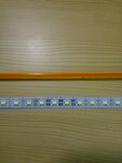
This is a part of China made Emergency Light and working for last one month. 36 LEDs on metal strips are arranged in 4 groups and drawing total around 800mA current. The LEDs look like slightly bigger SMD type. Surprisingly besides every LED on the strip 6Volt is written.(Very small modular LED? ). An on board SMPS is supplying around 7.5 volt to this part (connection points showing as "charger" in the picture). I made a replica of this circuit using 4 volt LED strips (12 LEDs) and a 4Volt 1amp rechargeable battery and using BD139. But what bothering me is that RC circuit supplying the base. Are they incorporating some sort of delay?

Forgot to mention, --- I am using my mobile charger for my 4volt version and is working
 

An emergency light is different from simply a battery charger.

The LEDs are supposed to drain the battery with the LED string matching the battery voltage or about 3V per LED in series. Each group needs a small R to limit the current. If I understand 4 groups of 8 as 4S8P that would need 12V not 6V for Vbat.

The supply -ve input is grounded to turn off the LEDs in event of a power failure.

While the pullup resistor base current needs to be about 2to 10% of the load current.

The Cap just slows the turn on/off rate.

These I know very well. Also, as I mentioned in the posts above, these are not simple LEDs that are known to have 1.7V to 3.2 V forward voltage. So I have attached a picture of 4 Volt version.Please see what is written near every LED. They are working without any resistance for months. May be they are some modular LEDs. So Series or Parallel connection was not my question.
All I want to know, in the circuit (post 1 above) what is the base current when the capacitor charges, and discharges? I want to know how to calculate biasing current in this case.
WP_000784.jpg
 
Last edited:

The capacitor will only charge to around 0V7. (Vbe) The base current is from 0 to around 9.4 mA. 0 while the capacitor charges, going up to 9.4 mA after the capacitor has reached Vbe.

The discharge current is defined by several factors, mainly the capacitor internal resistance and the type of charger. I would suppose that the charger will limit the current, since it must be some sort of trickle charger for the battery.
 

broken link removed

Your schematic shows 6V battery and 4 LEDs, with Rb=560 C=47uF and a D883 NPN Power with 2 diodes and a battery charger.
Missing is the connection from Vbat- to Vcharge-.

THe photo shows 4VLED on some FPC strip and appears to be all in parallel.

THe D883 specs are:
Collector-emitter saturation voltage V CE (sat) I C =2A, I B = 0.2A 0.5 V
Base-emitter saturation voltage V BE (sat) I C =2A, I B = 0.2A 1.5 V

This means to get 0.5V across Vce, you an need IC/IB= 10 i.e. the base current is 10% of the load.
When charging and the transistor disabled by shorting the lower diode to Vbat-, the current depends on the supply and battery ESR and voltage difference. THe capacitor current is limited by the base Resistor and voltage difference , hence 6V/560Ohm=10 mA
THis means the transistor can only drive 100 to 200mA total and the transistor Vce will rise to the difference between Vbat and Vled, which appears to be 2V.

I would expect each of these LED's can handle this amount 100~200mA. How many to do you have running> and what is your total current?
 
Last edited by a moderator:

.... Your schematic shows 6V battery and 4 LEDs, with Rb=560 C=47uF and a D883 NPN Power with 2 diodes and a battery charger.
Missing is the connection from Vbat- to Vcharge-.

The first diode will turn on and charge when the charge voltage is >6V(Vbat)+0,7V and the second will turn off the transistor a bit over 6V.

The battery will be charged with a voltage of 6V7-8 ish approx. the correct voltage for a SLA. Should be in the range 6V6 to 6V8 for a trickle charge, dependig on the ambient temperature.

When the charge voltage is less than Vbat, the LEDs will turn on.
 

I agree with Gorgon now. But the supply must be at least 7.5Vto 8V with 10% with otherwise the LEDs will spike on dim.

The Diodes are all in parallel, with none in series as shown and act as 4V Zeners to prevent overvoltage which if designed with internal resistors to raise Vf from 3.3V to 4V with a 0.7V power diode internally or are very poor LEDs with a large voltage drop.. (special?)

The transistor will get hot from >2V drop at 1A. (6.5-4=2.5)

The power supply must be carefully matched with the LEDs and battery voltage to prevent excess power dissipation.

When power is restored , the LEDs turn off immediately with the 2nd diode and then begin forward biasing the 1st diode. When the batteries reach full charge, the LED's may be on dim by a small pulse from each charge cycle at 100Hz? from the negative ripple of the supply , which is minimized with the 47uF cap when the 2nd diode no longer is forward biased.

Do your LEDs ever go dim when the battery is fully charged?
 

Status
Not open for further replies.

Part and Inventory Search

Welcome to EDABoard.com

Sponsor

Back
Top