erickson
Newbie level 3

- Joined
- Mar 24, 2013
- Messages
- 4
- Helped
- 0
- Reputation
- 0
- Reaction score
- 0
- Trophy points
- 1,281
- Activity points
- 1,318
Hello everybody!
I am building a microwave oscillator. At this moment, I finished the oscillator design with ideal lines, and I want to carry out the next step: Microstrip design. However, when I make the transformation for the different elements, from lines to Microstrip, the HB-Simulation issue a error like: "Circuit is stable. Found loop gain>1 but Nyquist criteria for oscillations not satisfied. This means that the loopgain poin 1+j0 was encircled in acounter clockwise direction..."
I have checked the date several times and it is correct, I think that the problem should be in the structure of the design. I mean, I would be to add more elements or, would be other modification.
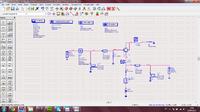
IDEAL LINES DESIGN (it works correctly)

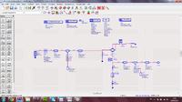
MICROSTRIP LINES.

The difference between both designs is: In the Microtrip Design, I added a MTEE and a MLIN (90degrees)(closest from the ports). These elements are not in the Ideal Lines Design, but I think these are totally necessary in Microstrip Design.
Enclosed you can find both designs.
Thank in advance.
I am building a microwave oscillator. At this moment, I finished the oscillator design with ideal lines, and I want to carry out the next step: Microstrip design. However, when I make the transformation for the different elements, from lines to Microstrip, the HB-Simulation issue a error like: "Circuit is stable. Found loop gain>1 but Nyquist criteria for oscillations not satisfied. This means that the loopgain poin 1+j0 was encircled in acounter clockwise direction..."
I have checked the date several times and it is correct, I think that the problem should be in the structure of the design. I mean, I would be to add more elements or, would be other modification.
IDEAL LINES DESIGN (it works correctly)

MICROSTRIP LINES.

The difference between both designs is: In the Microtrip Design, I added a MTEE and a MLIN (90degrees)(closest from the ports). These elements are not in the Ideal Lines Design, but I think these are totally necessary in Microstrip Design.
Enclosed you can find both designs.
Thank in advance.

