Continue to Site

Welcome to EDAboard.com

Welcome to our site! EDAboard.com is an international Electronics Discussion Forum focused on EDA software, circuits, schematics, books, theory, papers, asic, pld, 8051, DSP, Network, RF, Analog Design, PCB, Service Manuals... and a whole lot more! To participate you need to register. Registration is free. Click here to register now.

Tracking sin-wave with a random bias using CD4046

Status
Not open for further replies.

Jr9910

Newbie level 3
Joined
Sep 20, 2011
Messages
3
Helped
0
Reputation
0
Reaction score
0
Trophy points
1,281
Activity points
1,305
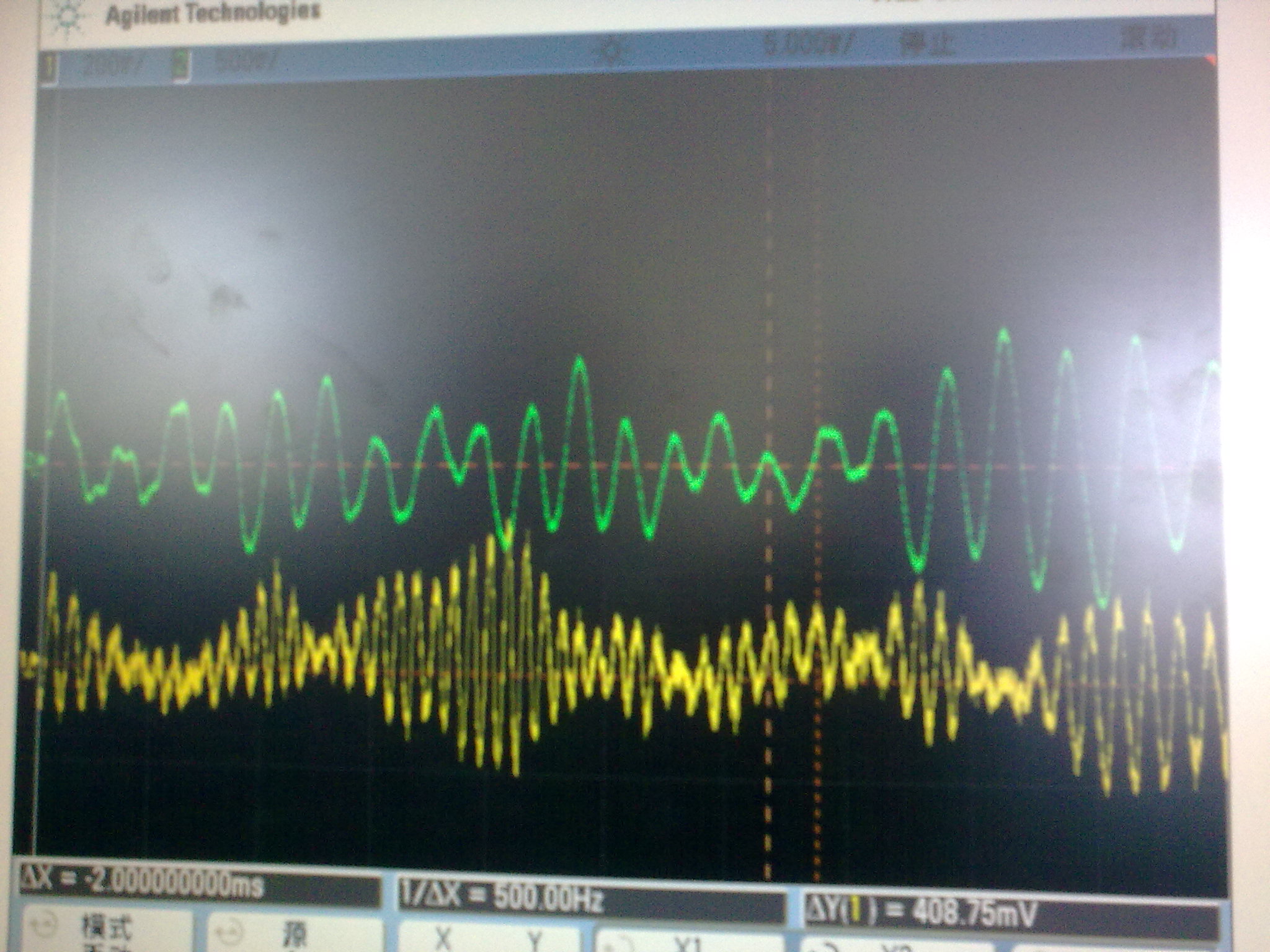
I captured the signals from the sensor, which is the sine waveform with a random bias of low frequency. I want to use the CD4046 consisting a narrow bandwidth filter tracking this signal and filter out the random bias. Is it possible ? Otherwise, if I use the Comparator II, its center frequency depends on the R1 and C1, is there any formula to calculate the f0 using R1 and C1 exactly ? I also want to know if I can design the filter bandwidth to 2~10Hz to filter the random noise, Because the capture range and the lock range doesn't relay on the parameter of the LPF using Comparator II. The signal with green color is the conditioning circuit output, which has a better performance. The yellow one is past a pull performance circuit.
 

Attachments

  • 20110920068.jpg
    20110920068.jpg
    496.8 KB · Views: 81

I once experimented with the 567 tone decoder which uses a PLL. It isn't the same as the 4046 but my observations might be of use.

I hoped I could use the 567 to reject off-frequencies. I hoped it would extract only the center frequency and turn it into clean DC pulses.

It didn't work that way. I got nothing resembling my original input signal.

The output only went high as long as it could detect the center frequency was dominant. The amplitude had to be at least .4V peak-to-peak.

I tried varying the input signal up and down a few cycles. The output became jittery.

It went high for a few cycles, then low for a few cycles. The cause was that the input was getting in and out of phase with the internal PLL.

When the difference got to be more than a few Hz, output went to zero continuously.

I found that what I needed was a narrow bandpass filter. I chose a bi-quad design, using 3 op amps. It worked well.

if I use the Comparator II, its center frequency depends on the R1 and C1, is there any formula to calculate the f0 using R1 and C1 exactly ?

You'll want to use a potentiometer to tune to the proper frequency. My data books show a 500k pot in the examples.

The formula is F = 1 / RC according to one book. Another has 1.1 / RC.
 

I found that what I needed was a narrow bandpass filter. I chose a bi-quad design, using 3 op amps. It worked well.
Does the narrow bandpass filter can track the center frequency changing signal ?
 

Please allow me to join in on this.

I am looking for a solution which might be very similar to yours.

The context:

A camera needs to get good images of a room with large variations in light level. There will be sunlight from outside an fluorescent from the inside.
Varying the camera's shutter duration will theoretically allow it to scale the intensity by a factor of 200 or more.
50uS --> lots of light, still not saturated
20mS --> reasonable sensitivity at low light levels.

now comes the problem. If there are fluorescent lights the shutter needs to be 10 or 20ms (50hz Europe) to always catch a full cycle of fluorescent light. If it is any different the camera will not be synchronized a the image will flicker.

I would like to find a way to synchronize to the sine wave of the fluorescent light in such a way that image acquisition will always start at the peak of the sine. That way I can use any shutter duration I like.

My idea is to measure the light level with a photo diode. If the sine wave caused by the fluorescent lights is > 5% of the total light level a PLL should pick up the sine and provide a synch pulse at each top. < 5% is less of a problem.
I can filter out the DC level (daylight) with a high pass filter, but still the sine waves intensity will vary between 5 and 100% of the signal.

Is this something a 4046 can do? I did read in the datasheet that it will support different signal amplitudes, but for this I would expect to need an auto gain stage as well.

Did any of you build anything similar to this?
 

When you amplify the photodiode signal, it may do for you to just amplify it to the max.

This will be possible if you can automatically amplify UPWARD the part of the waveform that is ABOVE a certain threshold, and amplify DOWNWARD the part of the waveform that is BELOW the threshold.

This should yield either pulses or square waves (depending on the device).

You may find this is adequate to trigger the camera.

As for the 4046, looking at the datasheet I see its output can resemble a square wave version of the input signal. I don't know how finicky it is about the input waveform.

It depends on which device gives you a pulse train suitable for triggering your camera.

You also have to figure out how to use one of those pulses, and just one, to trigger your camera.
 

My idea is to measure the light level with a photo diode. If the sine wave caused by the fluorescent lights is > 5% of the total light level a PLL should pick up the sine and provide a synch pulse at each top. < 5% is less of a problem.
I can filter out the DC level (daylight) with a high pass filter, but still the sine waves intensity will vary between 5 and 100% of the signal.
Do you use the PLL to pick up the sine? Which PLL chip do you have? The auto gain control maybe useful. If we just want to calculate the pulse times, maybe I can enlarge it to the rail to rail.
 

Do you use the PLL to pick up the sine? Which PLL chip do you have? The auto gain control maybe useful. If we just want to calculate the pulse times, maybe I can enlarge it to the rail to rail.

Yes, the plan is to pick up the "hidden" sine wave, lock on to it and then trigger the camera with this.
I was thinking about using the 4046 for this, but I am also looking into other options.

When you amplify the photodiode signal, it may do for you to just amplify it to the max.
This should yield either pulses or square waves (depending on the device).
You may find this is adequate to trigger the camera.

I am not too sure about this. I expect the signal to be polluted with other things like who knows, reflections of cars passing by, people walking by, maybe some extra light being turned on. I would feel a lot safer if I could use a PLL which will lock onto the sine in let's say 5 seconds and does not loose sync on any distortion which will last shorter than 1 second.

As for the 4046, looking at the datasheet I see its output can resemble a square wave version of the input signal. I don't know how finicky it is about the input waveform.

Yes, well that's was actually what my question was about.
Maybe I should combine both. Use the 50Hz from the light, amplify it to the max and use that as an input to the PLL.

It depends on which device gives you a pulse train suitable for triggering your camera.
You also have to figure out how to use one of those pulses, and just one, to trigger your camera.

That's kind of easy. There is a simple micro in the camera. I can make it count pulses and trigger every Nth pulse. The most important part is that the fluorescent lights will allways give about the same light level.
 

Status
Not open for further replies.

Similar threads

Part and Inventory Search

Welcome to EDABoard.com

Sponsor

Back
Top