strape81
Junior Member level 3

- Joined
- Dec 16, 2011
- Messages
- 25
- Helped
- 2
- Reputation
- 4
- Reaction score
- 2
- Trophy points
- 1,283
- Activity points
- 1,558
Hi Forum users,
I try to bring in my project all the advantages that a TFT Display with touchscreen promises. The touchscreen controller STMPE610 with the Displaytech's TFT Display, DT028ATFT-TS, are used but unfortunately till now I cannot make it work.The Initialisation commands are sent with I2C and it seems that works fine.
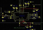
According to the attached schematic "TS-Controller_Circuit.JPG",

the IN2 and IN3 are not used and I connected them to the GND with a 10k resistor in between. The capacitors connected to the signal lines TFT_YU, TFT_YD, TFT_XR and TFT_XL are not 2pF but 2.2nF 0603. The interrupt signal TS_INT is connected to an MCU input (R8, pull-up resistor).
Now, getting to the point ... I have measured the following voltages with or without touching the surface, which is totally strange and I feel really uncomfortable about them...
Vio = 3.28V
V_XL or V_X- = 3.27V
V_XR or V_X+ = 0V
V_YU or V_Y+ = 0V
V_YD or V_Y- = 0V
and, of course, no interrupt is generated. What seems to be the problem? Probably is my misunderstanding of the controller, so pls could you tell me where I've got it all wrong???
Thanks a lot all of you, in advance!!!
P.S. This is the initialisation code
void STMPE610_Init(void)
{
__delay_cycles(1000);
STMPE610_Write(SYS_CTRL2, 0x0C); // Enable TSC and ADC Blocks
__delay_cycles(10);
STMPE610_Write(INT_EN, 0x01); // TOUCH_DETECT-Interrupt are enabled
__delay_cycles(10);
STMPE610_Write(ADC_CTRL1, 0x49); // 80 clock cycles for ADC conversion, 12-bit ADC and internal ref
__delay_cycles(10000); // delay 2ms
STMPE610_Write(ADC_CTRL2, 0x01); // ADC Clock = 3.25 MHz
__delay_cycles(10);
STMPE610_Write(GPIO_AF, 0x00);
__delay_cycles(10);
STMPE610_Write(TSC_CFG, 0x9A); // Average Control: 4 samples
// Touch detect delay: 500us
// Panel driver settling time: 500us
__delay_cycles(10);
STMPE610_Write(FIFO_TH, 0x01); // Not zero value
__delay_cycles(10);
STMPE610_Write(FIFO_STA, 0x01); // Clear the FIFO Memory Content
__delay_cycles(10);
STMPE610_Write(FIFO_STA, 0x00); // FIFO back to operation mode
__delay_cycles(10);
STMPE610_Write(TSC_FRACT_XYZ, 0x07);// Data Format for Z-Value
__delay_cycles(10);
STMPE610_Write(TSC_I_DRIVE, 0x01); // Choose 50mA driving channel
__delay_cycles(10);
STMPE610_Write(TSC_CTRL, 0x03); // Enable Device, No tracking index, X, Y, Z mode
__delay_cycles(10);
STMPE610_Write(INT_STA, 0xFF); // Clear all interrupt status
__delay_cycles(10);
STMPE610_Write(INT_CTRL, 0x03); // Enable the interrupts
__delay_cycles(10);
// define initial Touch Window
/*STMPE610_Write(WDW_TR_X, 0x0FFF); // Top Right X
__delay_cycles(10);
STMPE610_Write(WDW_TR_Y, 0x0FFF); // Top Right Y
__delay_cycles(10);
STMPE610_Write(WDW_BL_X, 0x0000); // Bottom Left X
__delay_cycles(10);
STMPE610_Write(WDW_BL_Y, 0x0000); // Bottom Left Y
*/
}
I try to bring in my project all the advantages that a TFT Display with touchscreen promises. The touchscreen controller STMPE610 with the Displaytech's TFT Display, DT028ATFT-TS, are used but unfortunately till now I cannot make it work.The Initialisation commands are sent with I2C and it seems that works fine.
According to the attached schematic "TS-Controller_Circuit.JPG",

the IN2 and IN3 are not used and I connected them to the GND with a 10k resistor in between. The capacitors connected to the signal lines TFT_YU, TFT_YD, TFT_XR and TFT_XL are not 2pF but 2.2nF 0603. The interrupt signal TS_INT is connected to an MCU input (R8, pull-up resistor).
Now, getting to the point ... I have measured the following voltages with or without touching the surface, which is totally strange and I feel really uncomfortable about them...
Vio = 3.28V
V_XL or V_X- = 3.27V
V_XR or V_X+ = 0V
V_YU or V_Y+ = 0V
V_YD or V_Y- = 0V
and, of course, no interrupt is generated. What seems to be the problem? Probably is my misunderstanding of the controller, so pls could you tell me where I've got it all wrong???
Thanks a lot all of you, in advance!!!
P.S. This is the initialisation code
void STMPE610_Init(void)
{
__delay_cycles(1000);
STMPE610_Write(SYS_CTRL2, 0x0C); // Enable TSC and ADC Blocks
__delay_cycles(10);
STMPE610_Write(INT_EN, 0x01); // TOUCH_DETECT-Interrupt are enabled
__delay_cycles(10);
STMPE610_Write(ADC_CTRL1, 0x49); // 80 clock cycles for ADC conversion, 12-bit ADC and internal ref
__delay_cycles(10000); // delay 2ms
STMPE610_Write(ADC_CTRL2, 0x01); // ADC Clock = 3.25 MHz
__delay_cycles(10);
STMPE610_Write(GPIO_AF, 0x00);
__delay_cycles(10);
STMPE610_Write(TSC_CFG, 0x9A); // Average Control: 4 samples
// Touch detect delay: 500us
// Panel driver settling time: 500us
__delay_cycles(10);
STMPE610_Write(FIFO_TH, 0x01); // Not zero value
__delay_cycles(10);
STMPE610_Write(FIFO_STA, 0x01); // Clear the FIFO Memory Content
__delay_cycles(10);
STMPE610_Write(FIFO_STA, 0x00); // FIFO back to operation mode
__delay_cycles(10);
STMPE610_Write(TSC_FRACT_XYZ, 0x07);// Data Format for Z-Value
__delay_cycles(10);
STMPE610_Write(TSC_I_DRIVE, 0x01); // Choose 50mA driving channel
__delay_cycles(10);
STMPE610_Write(TSC_CTRL, 0x03); // Enable Device, No tracking index, X, Y, Z mode
__delay_cycles(10);
STMPE610_Write(INT_STA, 0xFF); // Clear all interrupt status
__delay_cycles(10);
STMPE610_Write(INT_CTRL, 0x03); // Enable the interrupts
__delay_cycles(10);
// define initial Touch Window
/*STMPE610_Write(WDW_TR_X, 0x0FFF); // Top Right X
__delay_cycles(10);
STMPE610_Write(WDW_TR_Y, 0x0FFF); // Top Right Y
__delay_cycles(10);
STMPE610_Write(WDW_BL_X, 0x0000); // Bottom Left X
__delay_cycles(10);
STMPE610_Write(WDW_BL_Y, 0x0000); // Bottom Left Y
*/
}