ankitvirdi4
Member level 4
Hello all,
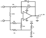
So this is my circuit,

Which is basically a current sense differential amplifier with a gain of 22.
The output of the circuit is as expected, (I get a DC sinewave within 3.3 peak with Vrms and Vpp varing according to the current of 0-6 Amps.).
I understood R1 R2 R3 R5 and R6 are used for the differential amplier configuration, R4 I guess is a current limiting resistor because voltage at the shunt is superimposed with 1.65V to shift it into positive cycle.
R7 and R8 act as resistor divider to generate 1.65V and the differential circuit itself is offseted by 1.65V.
I don't if my above stated understanding of the circuit is entirely correct. Please correct me where ever I am wrong.
Also, Will the resistor divider netwrok affect the gain? It does actually when I simulate the circuit in multisim. The gain changes by a small value about 22.019 for 1K and if R7 and R8 are changed to 10K the gain becomes 22.031 .
Why is this happening? I do not undertsand how to proceed with the transfer funtion calculation.
How do I find a definite formula for gain w.r.t R7 and R8, also R4 I don't know whether that would come in the picture too.
All the help is highly appreciated.
So this is my circuit,
Which is basically a current sense differential amplifier with a gain of 22.
The output of the circuit is as expected, (I get a DC sinewave within 3.3 peak with Vrms and Vpp varing according to the current of 0-6 Amps.).
I understood R1 R2 R3 R5 and R6 are used for the differential amplier configuration, R4 I guess is a current limiting resistor because voltage at the shunt is superimposed with 1.65V to shift it into positive cycle.
R7 and R8 act as resistor divider to generate 1.65V and the differential circuit itself is offseted by 1.65V.
I don't if my above stated understanding of the circuit is entirely correct. Please correct me where ever I am wrong.
Also, Will the resistor divider netwrok affect the gain? It does actually when I simulate the circuit in multisim. The gain changes by a small value about 22.019 for 1K and if R7 and R8 are changed to 10K the gain becomes 22.031 .
Why is this happening? I do not undertsand how to proceed with the transfer funtion calculation.
How do I find a definite formula for gain w.r.t R7 and R8, also R4 I don't know whether that would come in the picture too.
All the help is highly appreciated.