Continue to Site

Welcome to EDAboard.com

Welcome to our site! EDAboard.com is an international Electronics Discussion Forum focused on EDA software, circuits, schematics, books, theory, papers, asic, pld, 8051, DSP, Network, RF, Analog Design, PCB, Service Manuals... and a whole lot more! To participate you need to register. Registration is free. Click here to register now.

Timing circuit with NOR gates

Status
Not open for further replies.

Jester

Full Member level 6
Joined
Aug 18, 2012
Messages
377
Helped
7
Reputation
14
Reaction score
7
Trophy points
1,298
Location
.
Activity points
4,754
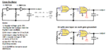
Can someone explain how the diode-resistor portion of this circuit works?

Note:

1) The schematic was determined by “beeping out” the traces on an existing PCB so there is a chance I missed something.

2) I used a 100:1 probe for the D1 signal to minimize loading.

cct.png
 

Status
Not open for further replies.

Similar threads

Part and Inventory Search

Welcome to EDABoard.com

Sponsor

Back
Top