Vermes
Advanced Member level 4
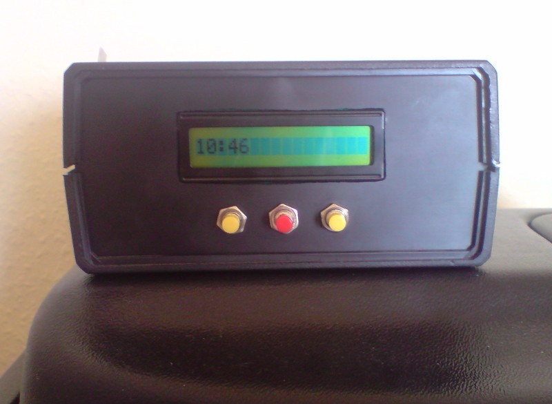
This is a design of time controller which is to turn on and off the lighting at a certain time. Another function of this controller is turning on another device once a day, also at a certain time. The controller can be expanded with another relays controlling the further devices.
Use:
- controlling the lighting and feeding in an aquarium
- controlling the lighting and watering in a greenhouse
- etc.
The device uses microcontroller PIC16F87 it controls two relays responsible for lighting and feeding fish at certain time. The real time is taken from the DS1307, which has stored settings in its non-volatile memory. Information is displayed on the screen of USART-LCD module. Control is via three reset-type buttons.
Construction:
The controller is powered from the mains. 230V is converter into 5V by the transformer. Voltage rectified by Graetz bridge (D3) passes through the stabilizer LM7805CT (U3) and is derived to the chips (IC1, U1) on the main board of the controller. Capacitors (C3, C5) are the filtering elements. Their value is at least 220uF for each amper of taken current. 5V is available on the socket (J3) and ports which allow you to connect external systems with data transmission I2C (J1), USART (J2).
Main board of the time controller:

Microcontroller PIC16F87 is the main component, which controls the operation of the device. The kind of microcontroller was chosen because of the number of I/O ports, which is enough to meet the assumptions of communication ports. The memory is also satisfactory (SRAM 368 bytes, EEPROM 256 bytes, FLASH 7168 bytes). The system closed in 18PIN PDIP housing is shown in the picture below. The microcontroller is equipped with I2C port (pins 7 SDA, 10 SCL) and USART (pins 11 TX, 8 RX).
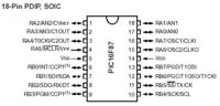
The system is clocked by external quartz oscillator with a frequency of 4MHz (maximum 20MHz) – pins 16 and 15, which can be skipped by using built-in oscillator which can operate with a frequency of 31kHz, 125kHz, 250kHz, 500kHz, 1MHz, 2MHz, 4MHz, 8MHz.
Control buttons (socket J5) were connected to RA port of the microcontroller (using pins 1, 2, 3). Resistors R6, R7 and R8 are the auxiliary ones, they stabilize the logic state. The remaining three pins (socket J5) can be used for connection additional control buttons or handling of additional external systems.
Sound communication is possible through a speaker with built-in generator, controlled by transistor (Q3) connected to the microcontroller (pin 9).
Relays are controlled by transistors (Q1, Q2) whose gates are connected through resistors (R5, R4) to the microcontroller (pins 12, 13). Transistors were protected using diodes (D1, D2) against overvoltage. Using relays allows to control the devices operating at high voltage and power, such as lamps, electrovalves.
Real time clock DS1307:
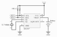
Main task of the microcontroller PIC16F87 is to control the relays and start the device at a certain time. DS1307 is the real time clock. Communication between the RTC and microcontroller is carried out via I2C bus. Operation of the clock even when turned off, is ensured by a battery with a voltage of 3V connected to the system (pin 3 plus, 4 GND). Chip detects power failure and switches to battery backup power. DS1307 has a non-volatile memory, in which settings of the device operation are stored. The clock requires the external crystal oscillator with a frequency of 32,768 kHz (pin 1, 2).
Link to original thread - Sterownik czasowy PIC16F87 i zegar czasu rzeczywistego