Continue to Site

Welcome to EDAboard.com

Welcome to our site! EDAboard.com is an international Electronics Discussion Forum focused on EDA software, circuits, schematics, books, theory, papers, asic, pld, 8051, DSP, Network, RF, Analog Design, PCB, Service Manuals... and a whole lot more! To participate you need to register. Registration is free. Click here to register now.

THX203 circuit not working

Status
Not open for further replies.

krishnakumar.r93

Member level 2
Joined
Jan 28, 2015
Messages
48
Helped
1
Reputation
2
Reaction score
1
Trophy points
8
Activity points
388
Hi

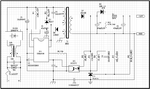
I have given connections as per the circuit, but i don't get output. Few components were not available, so i used some equivalent components. (SR3100 not available so i used MUR4100).

Only thing i did not use is the UU9.8 & DR6*8 inductor.

Will this affect my output? Is it definitely necessary?
 

Attachments

  • schematic thx 203.png
    schematic thx 203.png
    34.2 KB · Views: 538
  • THX203H.pdf
    553.6 KB · Views: 107

Your schematic appears to be a flyback converter. Everything has to be right if it is to work. Questions:

* What voltage do you get across C1?

* The datasheet states power supply spec as low voltage (9V or 16V, it's ambiguous). What voltage (Vcc) do you measure at pin 2?

* The IC receives its power supply from a winding on the transformer. This appears to be a case of unreliable startup, since the primary winding needs at least a cycle or two of On-Off switching, so that other windings generate voltage. Although the datasheet explains how the startup stage works, everything needs to be right in order for it to work.

* Can you confirm the IC is switching the primary on and off? Is the frequency within device specs? Is it within transformer specc?

* Did you try putting a full diode bridge on the secondary? Then observe which pair of diodes carries major current? This should tell you which diode to leave in the circuit.
 

Hi,

I assume the problem is not in the schematic. I rather assume it is in YOUR circuit.
I don´t check your alternative parts datasheets. I assume you already have checked them and found out that they are compatible.

! ! ! ! ! !

Safety first!

You know you have a circuit where all the circuit contains dangerous voltage.
For further tests I recommend to use an isolating tranformer at the input.

It really is dangerous. High voltage may hurt or kill you and / or others.

If you don´t have an isolating transformer, then stop reading here.

! ! ! ! ! !

I assume non of the users has a remote scope or DVM connectred to your circuit ;-)
Therefore you should measure some signals and tell us the results.

* all with respect to DC input signal GND = "-" connection of C1
* Voltage at C1: DVM, DC voltage
* Voltage at IC1, Pin2: DVM, DC voltage
* Voltage at IC1, Pin1: DVM, DC voltage
* Voltage at IC1, Pin8: Scope, DC

Then we will decide what the next steps will be...

Klaus
 

let me prepare another board and let you guys know as the one i used blasted near the transformer area.
 

Status
Not open for further replies.

Similar threads

Part and Inventory Search

Welcome to EDABoard.com

Sponsor

Back
Top