Enzy
Advanced Member level 1
Re: [moved] Query about VU meters (led bargraph)
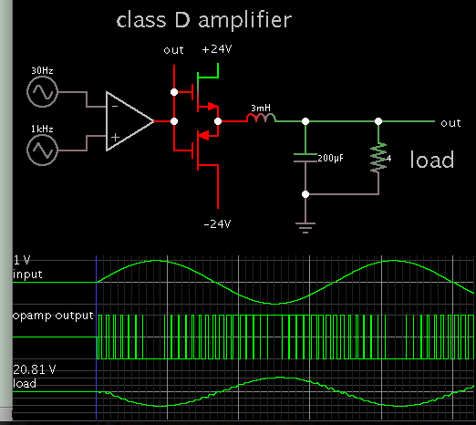
The amplifier I bought recently for my build I dont think its as poweful as the specs say it is I want to build a class D amplifier on my own, something with some Mosfets.
- - - Updated - - -
I am aware of the speaker set up, as I have done a couple of them over the years but building the amplifier is the part I want to learn.