Continue to Site

Welcome to EDAboard.com

Welcome to our site! EDAboard.com is an international Electronics Discussion Forum focused on EDA software, circuits, schematics, books, theory, papers, asic, pld, 8051, DSP, Network, RF, Analog Design, PCB, Service Manuals... and a whole lot more! To participate you need to register. Registration is free. Click here to register now.

third harmonic distortion in Current steering Dac

Status
Not open for further replies.

hamidyadegaramin

Newbie level 4
Joined
Dec 8, 2012
Messages
6
Helped
0
Reputation
0
Reaction score
0
Trophy points
1,281
Activity points
1,344
Hi
i have designed a 6-Bit second order Current steering DAC. As, one for MSB with total (1 m A) and the other one as the LSB (0.25 m A). the Data comes from a Sigma-Delta modulator with desired noise shaping figure.
i simulated both of DACs separately and compared their output with the inputs. there were no specific harmonic distortion. However, when i sum up their current (MSB + LSB), third order distortions appears.
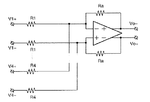
PS: i directly attach their outputs to each other and flow the current on a resistive load as shown in fig.
Undddtitled.jpg
 

Hi,

What about a scope picture?
Or tell us what magnitude is he distortion...

I assume it's just a clipping problem.

Klaus
 

Re: third order harmonic distortion in Current steering Dac

Hi,

What about a scope picture?
Or tell us what magnitude is he distortion...

I assume it's just a clipping problem.

Klaus
hi thanks for your reply
no the supply is 4V and the loads are 3K. no cliping is supposed
here is the difference between spectrum of ideal sum and sum of DACs
Capture.JPG
 
Last edited:

Capture.JPG
hi thanks for your reply
as seen in the pic it is not clipping. the figure includes ideal sum and summation by the DACs and spectrums.
thanks
 

Hi,

6bit .. how much SNR do you expect?

38dB seems to be not so bad.

Klaus
 

i expect that the PSD of the diff. outpu follow the ideal summation of LSB and MSB
 

However, when i sum up their current (MSB + LSB), third order distortions appears.

the figure includes ideal sum and summation by the DACs and spectrums.
What do you mean by "ideal sum" ?

i have designed a 6-Bit second order Current steering DAC.
As, one for MSB with total (1 m A)
and the other one as the LSB (0.25 m A).
the Data comes from a Sigma-Delta modulator with desired noise shaping figure.
Your DSM-DAC of ENOB=6bits are constituted from two Unit DACs ?

Each DAC sees other DAC's output impedance.
And output voltage level affects output impedance and current value.
I think this is a cause of distortion.

Is your DAC's Current Source Cascode ?

i directly attach their outputs to each other and flow the current on a resistive load as shown in fig.
Try to decrease resistive load.
 
Last edited:

i receive the MSB and LSB from a noise shaping modulator. ideally 4*MSB+LSB gives a noise shaped PSD. i did this in calculator of the cadence and Matlab both work in a same way. by means of ideal sum i meant this calculation.
however, when i do this summing by real DACs, i see a third and fifth order distortion.
i agree with you on effect of load. As i decrease the output voltage swing (decreasing the resistive load or decreasing the current), the distortion decreases.
ps: i use cascod current mirror
 

i agree with you on effect of load.
As i decrease the output voltage swing (decreasing the resistive load or decreasing the current), the distortion decreases.
If the resistive loads are pulled up to Vdd, increase Vdd value.

Or use summing amplifier to sum currents and convert their summation to voltage.
In attached figure, R1=0, R2=0, R3=0 and R4=0, since inputs are currents.
This scheme might cause even order distortions.
 

Attachments

  • 160516-215710.png
    160516-215710.png
    9.9 KB · Views: 105
Last edited:

Status
Not open for further replies.

Similar threads

Part and Inventory Search

Welcome to EDABoard.com

Sponsor

Back
Top