baby_1
Advanced Member level 1
Hello
i can find the thevenin resistance in circuit such as Cap , Inductor and resistor network but in the op-amp circuit how can i find the thevenin resistance across of the cap pins in these circuit that i imagine to find the thevenin resistance (because i want to design a amplifier and want to find the response frequency with the Cap , cut frequency but now it is important to me to find the thevenin resistance in op-amp circuit)(ideal op-amp and unideal op-amp)
Thanks
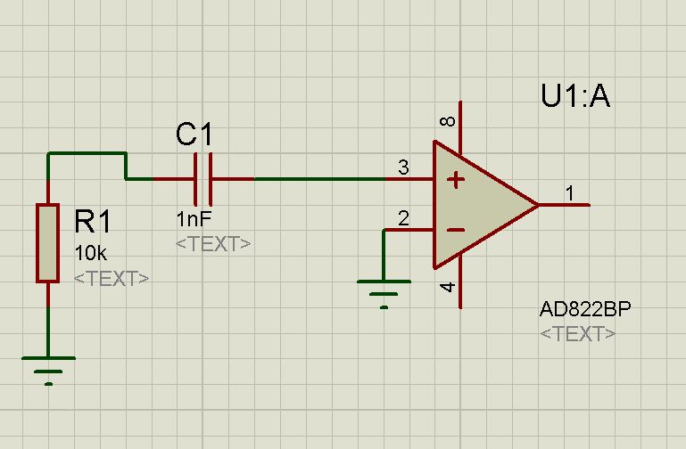
Question number 1:
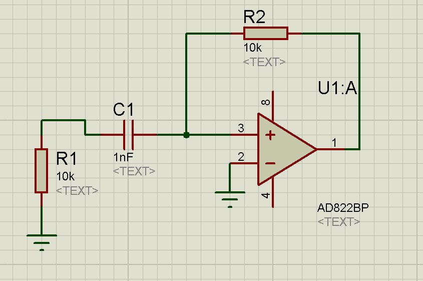
Question number 2:
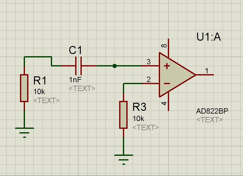
Question number 3:
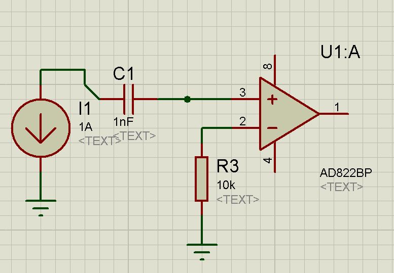
Question number 4:
i can find the thevenin resistance in circuit such as Cap , Inductor and resistor network but in the op-amp circuit how can i find the thevenin resistance across of the cap pins in these circuit that i imagine to find the thevenin resistance (because i want to design a amplifier and want to find the response frequency with the Cap , cut frequency but now it is important to me to find the thevenin resistance in op-amp circuit)(ideal op-amp and unideal op-amp)
Thanks
Question number 1:
Question number 2:
Question number 3:
Question number 4: