Continue to Site

Welcome to EDAboard.com

Welcome to our site! EDAboard.com is an international Electronics Discussion Forum focused on EDA software, circuits, schematics, books, theory, papers, asic, pld, 8051, DSP, Network, RF, Analog Design, PCB, Service Manuals... and a whole lot more! To participate you need to register. Registration is free. Click here to register now.

[SOLVED] The open loop DC gain

Status
Not open for further replies.

m_kuty

Member level 2
Joined
Mar 2, 2015
Messages
46
Helped
1
Reputation
2
Reaction score
1
Trophy points
8
Activity points
333
Hello everyone

Can any one help me in the Figure bellow,
1. Why are there capacitor (0.1u) and resistor (10M) in the circuit of the open loop response?
2. what the reason of there capacitor and resistor ?
3.what is the called this circuit?
4. and why the non-inverting feeding VDD/2?

op.jpg
 
Last edited:

Can any one help me in the Figure bellow,
1. Why are there capacitor (0.1u) and resistor (10M) in the circuit of the open loop response?
2. what the reason of there capacitor and resistor ?
The resistor provides DC negative feedback with a DC gain of 1.
This biases the op amp so the output doesn't saturate.

The capacitor prevents the source from connecting the input do DC ground and upsetting the bias.

The RC time constant is sufficiently long so that the test can go below 10Hz, where the op amp reaches its DC gain value
3.what is the called this circuit?
4. and why the non-inverting feeding VDD/2?
The circuit is called an op amp open-loop gain test circuit.
It actually tests the AC gain down to a very low frequency.

The VDD/2 connection is so that op amp input and output are biased at 1/2 the supply voltage (because of the non-inverting gain of 1), not at ground where standard op amps don't work.
 

The test circuit is flawed respectively isn't suited to measure the open loop frequency response. To achieve the plotted frequency response, the capacitor must have a factor 1e6 higher value.

Curiously the circuit can be found in the LM358/LM324 data sheet since more than 40 years.
 
  • Like
Reactions: m_kuty

    m_kuty

    Points: 2
    Helpful Answer Positive Rating
The test circuit is flawed respectively isn't suited to measure the open loop frequency response. To achieve the plotted frequency response, the capacitor must have a factor 1e6 higher value.
Good catch.
Yes, the impedance of the capacitor at the lowest test frequency must be less than the feedback resistance divided by the open-loop gain.
This requires a capacitor in the neighborhood of a farad for the feedback resistance and open-loop gain shown.
 
  • Like
Reactions: m_kuty

    m_kuty

    Points: 2
    Helpful Answer Positive Rating
Hi,

I´m not sure bout this.

The capacitor and the feedback resistor forms a differentiator circuit. (not a high pass filter with a -3dB corner frequency)
It has low gain with low frequencies and high gain at high frequencies.

This may be used to compensate for the first order low pass filter characteristic of the OPAMP.

The benefit is that the output voltage dynamic is not that big as without the differentiator circuit. During the whole bandwidth of the first order section the output voltage should be constant.

But indeed the circuit is not useful to measure DC gain. Additionally this is feedbacked circuit and not an open loop circuit.
As said: I´m not sure.

Klaus
 
  • Like
Reactions: m_kuty

    m_kuty

    Points: 2
    Helpful Answer Positive Rating
Thank you everyone and who has been contributed to answer my questions.
is there any disadvantages for using this particular circuit.

I need more about the Vdd/2 on non-inverting. more expansions

- - - Updated - - -

Hi,

I´m not sure bout this.

The capacitor and the feedback resistor forms a differentiator circuit. (not a high pass filter with a -3dB corner frequency)
It has low gain with low frequencies and high gain at high frequencies.

This may be used to compensate for the first order low pass filter characteristic of the OPAMP.

The benefit is that the output voltage dynamic is not that big as without the differentiator circuit. During the whole bandwidth of the first order section the output voltage should be constant.

But indeed the circuit is not useful to measure DC gain. Additionally this is feedbacked circuit and not an open loop circuit.
As said: I´m not sure.

Klaus


To measure the DC gain in the open loop for this circuit is the output node and the node between the resistor and capacitor.
 

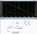
Here's an LTspice simulation of the circuit with capacitor values of 0.1µf and 1f.

As Klauss noted, the capacitor acts as a differentiator, but that's only until the differentiator gain reaches the open loop gain of the op amp
For the 0.1µf cap, this occurs at about 400Hz (green trace).
After that, and the resonant peak, it follows the open-loop gain versus frequency curve.

The 1f capacitor value has a differentiator gain equal to the open loop gain at below 0.1Hz, so the output follows the open-loop gain all the way (yellow trace).

Capture.PNG
 
  • Like
Reactions: m_kuty

    m_kuty

    Points: 2
    Helpful Answer Positive Rating
Status
Not open for further replies.

Part and Inventory Search

Welcome to EDABoard.com

Sponsor

Back
Top