Continue to Site

Welcome to EDAboard.com

Welcome to our site! EDAboard.com is an international Electronics Discussion Forum focused on EDA software, circuits, schematics, books, theory, papers, asic, pld, 8051, DSP, Network, RF, Analog Design, PCB, Service Manuals... and a whole lot more! To participate you need to register. Registration is free. Click here to register now.

Testbench StateX

Status
Not open for further replies.

KingMoshe

Member level 2
Joined
Aug 10, 2021
Messages
48
Helped
0
Reputation
0
Reaction score
0
Trophy points
6
Activity points
362
Hi all,
I made a testbench to test my module and I see weird behavior.
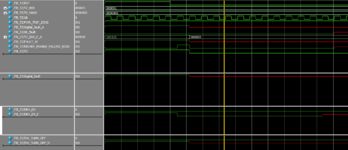
please look at the signal INV_TURN_OFF and INV_TURN_OFF_N.
The relation between the two signals is: INV_TURN_OFF_N = ~INV_TURN_OFF.
I don't understand why the signal INV_TURN_OFF_N got value StX.
1635927104151.png

1635927074214.png
 

Attachments

  • 1635927018136.png
    1635927018136.png
    54.6 KB · Views: 103

I suspect there are more drivers for INV_TURN_OFF_N. Show the full code.

In Modelsim, you have a track 'X' function.
 

I suspect there are more drivers for INV_TURN_OFF_N. Show the full code.

In Modelsim, you have a track 'X' function.
Hi, There is no more drivers for INV_TURN_OFF_N
 

Hi,

from the given simulation result, I agree with FvM ... and expect the problem in the (whole) code.

--> Show us the whole code, then we are able to find the problem.

Klaus
 

Hi,
Sorry, you are right, I have more logic, so I will try to explain better:
This is the relation between INV_TURN_OFF to INV_TURN_OFF_S (S = synchronizer output)
The picture below taken from module that have into it the the sync module:
1635948057177.png

1635948303005.png

and the is the code:
Code:
always @ ( posedge clk )
    begin
        if (RST) temp <= SYNC_VAL ;
        else temp <= D ;
    end
      
always @ ( negedge clk )
    begin
        if (RST) Q <= SYNC_VAL ;
        else Q <= temp ;
    end


Now, I don't understand why I see the blue HiZ in the sync output.
If I simulate only the sync module the relation between input to output looks fine.
Here example to the sync module simulation:
1635948413182.png
 
Last edited by a moderator:

Hi,

what is "SYNC_VAL" .. and where is it defined?

Klaus
 

please see:

Code Verilog - [expand]
1
2
3
4
5
6
7
8
9
10
11
12
13
14
15
16
17
18
19
20
21
22
23
24
25
26
27
28
29
30
31
module SYNC_INPUT (D,
                    clk,
                    RST,
                    //output
                    Q
                    ) ;
 
parameter SYNC_VAL = 1'b0;    //a default value output during RST (immediately after RST)               
// Inputs
input wire D;
input wire clk;
input wire RST;
 
//Outputs
output reg Q ;
 
reg temp ;
 
 
always @ ( posedge clk )
    begin
        if (RST) temp <= SYNC_VAL ;
        else temp <= D ;
    end
   
   
always @ ( negedge clk )
    begin
        if (RST) Q <= SYNC_VAL ;
        else Q <= temp ;
    end

 
Last edited by a moderator:

Hi,

here a snippet, there a snippet...

you don´t do yourself a favour.

Klaus
 

Hi,

here a snippet, there a snippet...

you don´t do yourself a favour.

Klaus
I tried to be the most focused and clear

The last one is the full code.
 

Your second and following posts have little to do with the original post. In the original post, INV_TURN_OFF_N is combinational, driven by assign statement.

Now you have clocked registers. How about the original problem, is it solved, or did you report it incorrectly?

As for the synchronizer in the last post, you should show the module instantiation with the respective test bench. But there's no instantiation of synchronizer in second post...
 

@KingMoshe
There is a simple rule here....if you provide less or incomplete info, you get less or partial help!
 

Status
Not open for further replies.

Part and Inventory Search

Welcome to EDABoard.com

Sponsor

Back
Top