Vermes
Advanced Member level 4

- Joined
- Aug 2, 2011
- Messages
- 1,163
- Helped
- 0
- Reputation
- 0
- Reaction score
- 0
- Trophy points
- 1,316
- Activity points
- 22,318

Assumptions of the presented here circuit:
- 24V supply
- standard current output 4mA-20mA
- input stage implemented on OP07
- A/C ICL7107 or ICL7106 converter for temperature measure
- measurement error no greater than 2,5%
Description of the circuit:
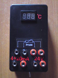
The circuit is the temperature gauge that uses platinum resistor PT-100 as measure sensor. Range of measured temperatures is between 0 and 300 degrees Celsius. Measurement error for the circuit is equal 1%. It is possible to measure temperature for the sensor by four- and two-wire connection (switch visible on bottom of the housing).
The whole can be powered with 12V-30V (thanks to applying voltage stabilizers 7809 – U6 and 7805 – U7). The circuit was also equipped with voltage converter ICL7660 (U8) in order to gain negative supply voltage -5V to power the section of operational amplifiers and A/C converter. Also two circuits (U3, U5) of precise voltage source were designed at 1,8V.
Input part of the gauge consists of a current source based on LM334 (U4), which supplies the gauge with constant current 1mA and precision operational amplifier OP07 (U1). Current source was designed with temperature compensation. For this purpose, an additional rectifier diode and a potentiometer for fine adjustment of the current value were applied.
Amplifier OP07 operates in a differential system, measuring the voltage drop on the PT-100. Input voltage range is 100mV-212mV, respectively for temperatures 0-300 degrees Celsius. This signal is amplified by 10-fold (1V-2, 12V) and fed to the voltage divider (R5, R6, 4-fold) and directly to the input (U2) of the system adjusting-converting voltage to current.
Voltage from the divider (250mV-530mV) is fed to the input In+ of ICL7107. Input In- is connected to the reference voltage 250mV (divider R35, R36), equal to the lower limit of the In+ voltage. This procedure is to shift the characteristics of the input voltage down, so that it passes through zero. The reference voltage for the A/C converter (REF LO and REF HI) can be set using a voltage divider R24 and R25 at about 933mV.
In order to gain current output for standard 4mA-20mA, U/I converter system based on Howland pump of double operational amplifier TL072 was implemented. One of the amplifiers operates as a voltage level shifting system. The input voltage is reduced by the value 720mV (derived from the voltage divider R11, R12, R13 connected to the second reference voltage) and amplified approximately 1,42 times. In this way we get a signal 0,4V-2V at the output, which is fed to the Howland pump (second amplifier TL072 with additional transistor T1 increasing the maximum output current). The output current is determined as the ratio of pump input voltage to R19.
Calibration of the gauge consists of an appropriate setting the voltage levels by means of potentiometers R12, R23 and R31. The temperature may be set by a decade resistor (100Ω - 0°C, 212Ω – 300°C). The first step is to adjust the voltage of the supply current of the PT-100 sensor to 1mA by turning the potentiometer R23. The next step is to measurement the output current 4mA-20mA and for the maximum ranges, set as close as possible current values using R12. Final calibration is based on adjusting the display for the A/C. For maximum range (0-300) you can set the smallest possible deviation by R31. Properly calibrated meter should not exceed 1% error for both the display and the output current (using resistors 1%).
Link to original thread (useful attachment) - Miernik temperatury dla czujnika pt100