Continue to Site

Welcome to EDAboard.com

Welcome to our site! EDAboard.com is an international Electronics Discussion Forum focused on EDA software, circuits, schematics, books, theory, papers, asic, pld, 8051, DSP, Network, RF, Analog Design, PCB, Service Manuals... and a whole lot more! To participate you need to register. Registration is free. Click here to register now.

Tantalum capacitors damage problem

Status
Not open for further replies.

Vasilevski

Junior Member level 2
Joined
Jan 11, 2017
Messages
20
Helped
5
Reputation
10
Reaction score
4
Trophy points
3
Location
Minsk
Activity points
255
Hello all.

Straight to the point. I work for an electronics company. We deal with a manufacture of power supplies 1-4kW. We have a tantalum capacitors malfunction problem from time to time. We usually use AVX or Kemet tantalum capacitors. An annual consumption of the capacitors usually is around 60 000 psc. An annual amount of the malfunction capacitors I would say is in a range of 0.05-0.15% of the annual consumption. The supply chain includes only official dealers ala Digikey or similar, so I'm sure that counterfeit parts are not the reason of the problem. I haven't been able to find any correlation between a batch number of the capacitors or a location on PCBs and the tantalum capacitors malfunction. Sometimes we do not see any problems with the capacitors for a month and than have 5-20 cases of the malfunction in a few days. As to the circumstances of the malfunction, I can say, that 90-95% of the tantalum malfunction are burnouts of the capacitors during the first time power supply appliance. Possibly, the most plausible reasons of the malfunctions are manufacturing defects or some issues with the reflow temperature profile during a soldering process (though, it was chosen in accordance with manufacturers recommendations). So here my questions:

1. Have you ever faced with a similar problem? It would be great if you could share your experience.
2. How would you assess "normal" amount of manufacturing defects for tantalum capacitors?
3. Do you have an experience of eliminating the reasons of electronics parts damage during a solder reflow process? What would you recommend?

I would appreciate any ideas or thoughts! Thanks in advance!
 

Do you see tantalum capacitor failure in all positions or only with capacitors that are exposed to higher inrush currents, e.g. during power-up? Failure of tantalum capacitors due to current stress won't be surprizing.
 
Do you see tantalum capacitor failure in all positions or only with capacitors that are exposed to higher inrush currents, e.g. during power-up? Failure of tantalum capacitors due to current stress won't be surprizing.
Hi. Thanks for the answer!
It seems like the problem is not related to inrush currents since it appears in different PCBs in different places. Nevertheless, we considered that it can be an issue and conducted the following experiment. We have different types of PCBs where we have faced the problem. So we took one PCBs from the type in which we saw the problem before and applied 24Vdc (all the capacitors are 35Vdc range) directly to the capacitors on the PCB. Then we switched 24Vdc on and off around 1000 times. Nothing happened. Then we disconnected 24Vdc and applied mains (110Vac) to the PCB (as it was during previous malfunction cases) and swithed it on and off around 1000 times. The same outcome - nothing happened. In both cases the capacitors had enough time to charge and discharge completely.
So, I assume the inrush currents is not the issue.
 

As to the circumstances of the malfunction, I can say, that 90-95% of the tantalum malfunction are burnouts of the capacitors during the first time power supply appliance.
Well that's fortunate, this means most of the defects shouldn't escape the factory so long as you do basic testing.

Have you tried to rule out whether the failures are related to other variations in nearby components on the same board? If you have a board which experienced the failure, and you replace the bad capacitors, does the fault occur significantly more often than other boards?
 
Reverse insertion is an easy way to make popcorn. Is this inspected when caps fail? Probably not the issue if assembly is T,&R but manual board stuffing brings human error into the picture.
 
You may have to consider testing all capacitors at their rated voltage (35V, not 24V) while measuring leakage at incoming inspection to see if that spots any failures.
 
It's usually process related design flaws as all parts are 100% tested OK
Review the SMT thermal profiles against vendor recommendations. And report back thru buyers with a Root Cause Failure Analysis and yied repair costs to request better SMT thermal margin specs on peak temp duration product time or request Process Engineers to fix the problem with your own advice on liquidus Temp max * time duration. The PE's have the tools to connect thermocouples in a "boat" during reflow to case using kapton tape.

Review Kyocera's findings and recommendations for solder with 240'C max and increased failures at 245 to 250'C https://www.kyocera-avx.com/docs/techinfo/LeadFree/leadfr.pdf
 
Last edited:
Static shocks can affect tantalums - you may not see the effects straight away but the static over-voltage or reverse voltage on the pins can and does affect their lifetime ... also running them too close to rated volts ...
 
Hi,

Mechanical stress may also reduce lifetime:
--> micro cracks may enable humidity (air) to go inside --> long time failure

But I think that peak currents or voltage overshots may be more likely.

What's the whole application? Are motors involved? Switch mode regulators with stability problems?

Are the capacitors tested before assembling? In your company or the assembling company?
Are the boards tested / programmed?
(Just to exclude that the stress did not happen during testing/programming.)

Klaus
 
Well that's fortunate, this means most of the defects shouldn't escape the factory so long as you do basic testing.

Have you tried to rule out whether the failures are related to other variations in nearby components on the same board? If you have a board which experienced the failure, and you replace the bad capacitors, does the fault occur significantly more often than other boards?
Hi,
Yes, it's really fortunate. The failure rate due to the tantalum capacitors on a customer side is around 0,0005%.
Yes, we tried to figure out is there any coherence between the failures of the capacitors and the components nearby but it seems that there is not.
If we replace the capacitors that have burned out, a failure usually does not appear any more on this board.
Thanks for your questions and thought!
--- Updated ---

Reverse insertion is an easy way to make popcorn. Is this inspected when caps fail? Probably not the issue if assembly is T,&R but manual board stuffing brings human error into the picture.
or into the picture.
Hi,
No, a reverse insertion is not the our issue either. We use a manual soldering only for R&D PCBs. All the other assemblies (those in question) are soldered in an automated process.
Thanks for the idea and for making me smile at your comparison of capacitors burnouts with popcorn:)
--- Updated ---

You may have to consider testing all capacitors at their rated voltage (35V, not 24V) while measuring leakage at incoming inspection to see if that spots any failures.
Hi,
Thanks for the ideas!
I'm not sure if this is a good idea to test the caps using their rated voltage since tantalum caps are very sensitive to overvoltage and there are recommendations to use voltage derating (usualy ~ 80% of their rated voltage) to maintain reliability.
As to testing leakage currents it seems it worth trying. However, there will be some difficulties with testing leakage currents directly in a reel.
 
Last edited:

Review Kyocera's findings and recommendations for solder with 240'C max and increased failures at 245 to 250'C https://www.kyocera-avx.com/docs/techinfo/LeadFree/leadfr.pdf
Hi,
Thanks a lot for the tech paper from Kyocera. I'll discuss it with our PE's. For now I can say, that the Peak temperature of reflow for lead free process is set to 250C for our assemblies.
Possibly, it can lead to a higher failure rate of the caps.
Now I'm thinking of gluing 50-100 caps to an empty (without cuprum) board and measuring the leakage currents before and after the reflow. Hopefully, we will find something.
--- Updated ---

Static shocks can affect tantalums - you may not see the effects straight away but the static over-voltage or reverse voltage on the pins can and does affect their lifetime ... also running them too close to rated volts ...
Hi, Thanks for the ideas!
Since we use automated soldering process I believe, that static electricity is not the issue. In addition to that from my expertise tantalum caps are not too sensitive to static as the other components (for instance, transistors with low gate capacity). As we don't have similar problems with the other components I assume we can exclude the static as the reason of the failures.
We use the caps at 70% of their rated voltage. So it is not the issue either.
 
Last edited:

Hi,

Mechanical stress may also reduce lifetime:
--> micro cracks may enable humidity (air) to go inside --> long time failure

But I think that peak currents or voltage overshots may be more likely.

What's the whole application? Are motors involved? Switch mode regulators with stability problems?

Are the capacitors tested before assembling? In your company or the assembling company?
Are the boards tested / programmed?
(Just to exclude that the stress did not happen during testing/programming.)

Klaus
Hi,
Thank you for your reply!
I agree with you upon mechanical stress. Nevertheless, analysing our manufacturing process, I can think of the only reason of getting micro cracks and it is too rapid cooling after solder reflow. I have discussed this idea with our Process Engineers and they have assured me that it doesn't exceed 2°C/s whereas max recommended cooling gradient should be less than 5°C/s.
Here my answers to your questions:
- The PCBs in question are different parts of different switching supplies modules (SSM). Some of them are SSM itself. Motors are not involved.
- No, the caps are not tested before assembling process. We relay on our transparent supply chain from manufacturers (Kemet and AVX) to us and their reputation. Perhaps, we should.
- Boards are 100% tested. We usually "catch" around 99,9995% of all malfunctions related to the tantalum capacitors problem on our side. Nevertheless, it takes time to deal with the problem in our manufacture. We have not understand the reason of the caps failure yet. This raises some concerns that slight deviations in our manufacturing cycle can lead to significant increase of a failure rate on a client's side, which is not acceptable.
--- Updated ---

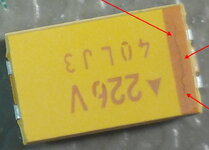
I have asked our PCB assemby manufacture to take a closer look at tantalum capacitors before and after a reflow process. They found some strange marks which look like micro cracks during PCBs quality control. They are present at tantalum capacitors in reel and PCBs.
I'm not sure if this defect of a paint or it is actually crack. Have you seen something like that before?
 

Attachments

  • Tantalum cap.jpg
    Tantalum cap.jpg
    196.1 KB · Views: 112
Last edited:

Mechanical stress may also reduce lifetime:
--> micro cracks may enable humidity (air) to go inside --> long time failure
If there are micro cracks and some moisture has got into the devices then it could be that the rapid heating during reflow could be part of a failure mechanism.
 
Hi,
Yes, it's really fortunate. The failure rate due to the tantalum capacitors on a customer side is around 0,0005%.
Yes, we tried to figure out is there any coherence between the failures of the capacitors and the components nearby but it seems that there is not.
If we replace the capacitors that have burned out, a failure usually does not appear any more on this board.
Thanks for your questions and thought!
--- Updated ---


Hi,
No, a reverse insertion is not the our issue either. We use a manual soldering only for R&D PCBs. All the other assemblies (those in question) are soldered in an automated process.
Thanks for the idea and for making me smile at your comparison of capacitors burnouts with popcorn:)
--- Updated ---


Hi,
Thanks for the ideas!
I'm not sure if this is a good idea to test the caps using their rated voltage since tantalum caps are very sensitive to overvoltage and there are recommendations to use voltage derating (usualy ~ 80% of their rated voltage) to maintain reliability.
As to testing leakage currents it seems it worth trying. However, there will be some difficulties with testing leakage currents directly in a reel.
Long term you should derate but rated is rated and the part should both stand up, and not leak with an "out of family" I-V. To me the most "interesting" are units which have a leakage step prior to spec limit voltage, that might indicate a pinhole or thin spot that passes a production spec, but its lot-mates are all much lower and "culls" are allowed to inhabit the slack, because numbers.

If you do 100% IQC test on reeled capacitors then you could read & record and post-scrub data to find hidden t=0 "good", but doomed, units by out-of-family criteria but what you'd do to skip reel positions or whatever, is some sort of yield improvement exercise (and probably costs 10X the shipped unit cost, not accounting for up front engineering). I'm sure you won't come close to AVX's test cost per unit in a board production environment.
 
Long term you should derate...
Sorry, I havent got what we should derate on your opinion.
If you meant the voltage that is applied to the tantalum capacitors, I can say that we apply 70% of the rated voltage which is more than enough since the manufacturers recommend only 20% margin.
If you do 100% IQC test on reeled capacitors
We don't do 100% IQC test on reeled capacitors. We do 100% test of soldered assemblies. We won't be able to do 100% IQC test of the caps on a regular basis since it will rise costs to unacceptable level.
An idea is to find out the reason of the problem with the tantalum capacitors to be able to tune our manufacturing processes to be sure that we don't sell our devices with unacceptable failure rate. In the other words, we want to be sure, that we can "catch" the overwhelming majority of the capacitor’s failures on our side.
We can test a bunch of the caps (manually or semi-automatically) to find out if there are some outliers in terms of leakage currents before and after a reflow process. Possibly, this would clarify if we faced up with a problem with the caps themselves or with an unappropriated reflow temperature profile.
 

I agree with G4BCH's diagnosis, I suspect moisture is out-gassing as the temperature suddenly rises during the soldering process. If possible try baking them (as you would do with stored ICs) for a few hours before assembly to reduce moisture content.

Whether or not that is the cause of the failures is difficult to tell but given the relatively high fail rate it should be easy to see if it makes a difference.

Brian.
 
Status
Not open for further replies.

Similar threads

Part and Inventory Search

Welcome to EDABoard.com

Sponsor

Back
Top