cupoftea
Advanced Member level 5
Hi,
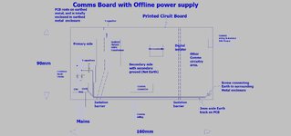
Do you agree, that the attached shows where the Y capacitors must be connected/placed in order to improve EMC on this comms board, which has an offline SMPS on it?
Do you also agree, that the position of the Earth screw is totally wrong?….and creates a big “high frequency AC” Earth loop? The Earth screw should actually be as close to the incoming mains earth wire as possible.
In any case, we are not at liberty to move the earth screw now anyway.
Ayk, the position of the Y caps is purely to provide a low impedance path for emissions to remain in the Line_to_Neutral loop. (ie, instead of radiating away to the surrounding earth) The Y capacitors simply “invite” high frequency emissions to come back out of the earthed enclosure, and go back down the Line/Neutral. Any other connection of the three shown Y capacitors would be less optimal, would you agree?