amitesh43
Newbie level 5

- Joined
- Nov 27, 2013
- Messages
- 9
- Helped
- 0
- Reputation
- 0
- Reaction score
- 0
- Trophy points
- 1
- Location
- sweden
- Activity points
- 56
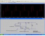
i was trying to design a sychronous bridge rectifier. i started like instead of replacing all the 4 diodes at
a time in the circuit,only 2 of them are replaced by mosfets and remaining 2 are diodes.while simulating
i was seeing some unwanted current peaks are coming can anyone explain y they are coming and is their
any solution for avoiding them i am attaching circuit related pics.....?
INPUT Voltage=155Vp-p
LOAD 45w