Continue to Site

Welcome to EDAboard.com

Welcome to our site! EDAboard.com is an international Electronics Discussion Forum focused on EDA software, circuits, schematics, books, theory, papers, asic, pld, 8051, DSP, Network, RF, Analog Design, PCB, Service Manuals... and a whole lot more! To participate you need to register. Registration is free. Click here to register now.

Switches and Power Supply

Status
Not open for further replies.

tehrealbinglebob

Newbie level 6
Joined
May 10, 2011
Messages
11
Helped
0
Reputation
0
Reaction score
0
Trophy points
1,281
Activity points
1,358
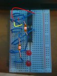
Okay so I want to make a ripple carry adder. I have and XOR and AND IC's and they are wired up but I want to use switches for toggling the inputs. I bought two to test it out but they are a lot bigger than I thought so I don't think I can use them. Also I have a power supply that uses two AA batteries. Is that not enough to power something like this? It's not done yet either this is just a half adder.

**broken link removed**
 

2 AA batteries equals only 3V. Use a 9V plus a regulator (e.g LM7805).
 

Need to change some wires in the circuit.
See details:
 

Attachments

  • corrections to circuit.JPG
    corrections to circuit.JPG
    43.3 KB · Views: 67
Okay so i do need more power... and the switches? Also what does using a resistor do? And mister_rf what changes so I need to make?

EDIT Nevermind, I saw the attachment but again what do resistors do?
 
Last edited:

Alright thanks! One last thing, The top IC in the picture is an XOR. Why is it that basically the output is on all the time to matter the inputs? Two ground, two Vcc in, or opposites(which is the only time its supposed to light up).
 

From the picture I can't see the code number for the circuits. Please provide type of each circuit.
 

The top is CD74HC86E and the bottom is M74LS08P, but the bottom one works fine.
 

The Exclusive-OR (XOR), performs the following logic operation:
X \[\oplus\] Y = X Y’ + X’ Y
(Operator uses the symbol \[\oplus\] )

So the result is 1 only when either X is equal to 1 or Y is equal to 1, but not when both X and Y are equal to 1.

One 74HC86 circuit contains quad 2-input Exclusive-OR gates, datasheet here:
**broken link removed**

So if you want to use a single gate, use for example inputs pin 1 and pin2 and for the output pin3.
GND pin 7
and
Vcc pin 14

---------- Post added at 22:27 ---------- Previous post was at 22:19 ----------

By the way, if you want to test the circuits using some LEDs, yes, you can use a simple switch, as you may ignore the additional pulses due to bouncing contacts.
 

Yeah Thats how I have it set up. But even when I have no wires for input at all the LED still turns on.

As you can see here:

**broken link removed**

I have no inputs but the LED still turned on.
 

If you connect the LED without resistor you may destroy the circuits.
Practically there are two possibilities to connect some LED on gates output.
-One connection type to use one pin for gate output the other pin to the GND, in this situation the LED will be ON only if output = level ‘’1’’
-Second connection for LED, one pin to Vcc, the second one to the gate output, in this situation the LED will be ON if the output = level ‘’0’’.
And for the TTL circuits, no connection on input, equal to situation as a level high (‘’1’’) applied on input, so the circuits reacts without any wire connected.
 

Status
Not open for further replies.

Similar threads

Part and Inventory Search

Welcome to EDABoard.com

Sponsor

Back
Top