Continue to Site

Welcome to EDAboard.com

Welcome to our site! EDAboard.com is an international Electronics Discussion Forum focused on EDA software, circuits, schematics, books, theory, papers, asic, pld, 8051, DSP, Network, RF, Analog Design, PCB, Service Manuals... and a whole lot more! To participate you need to register. Registration is free. Click here to register now.

swicthing power supply

Status
Not open for further replies.

erchiu

Member level 5
Joined
Apr 7, 2012
Messages
93
Helped
2
Reputation
4
Reaction score
1
Trophy points
1,288
Location
Rome - Italy
Activity points
2,082
hi everyone,
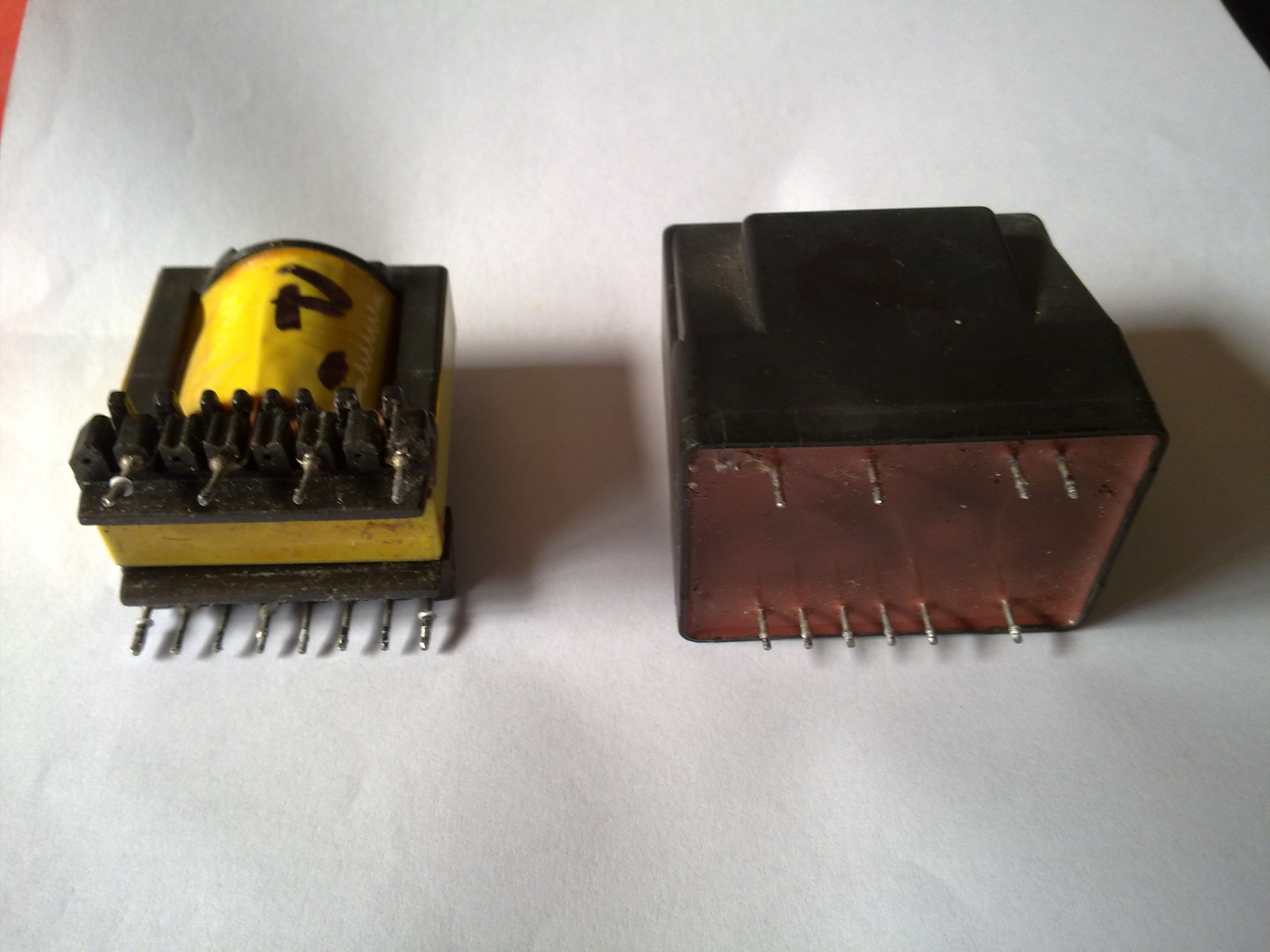
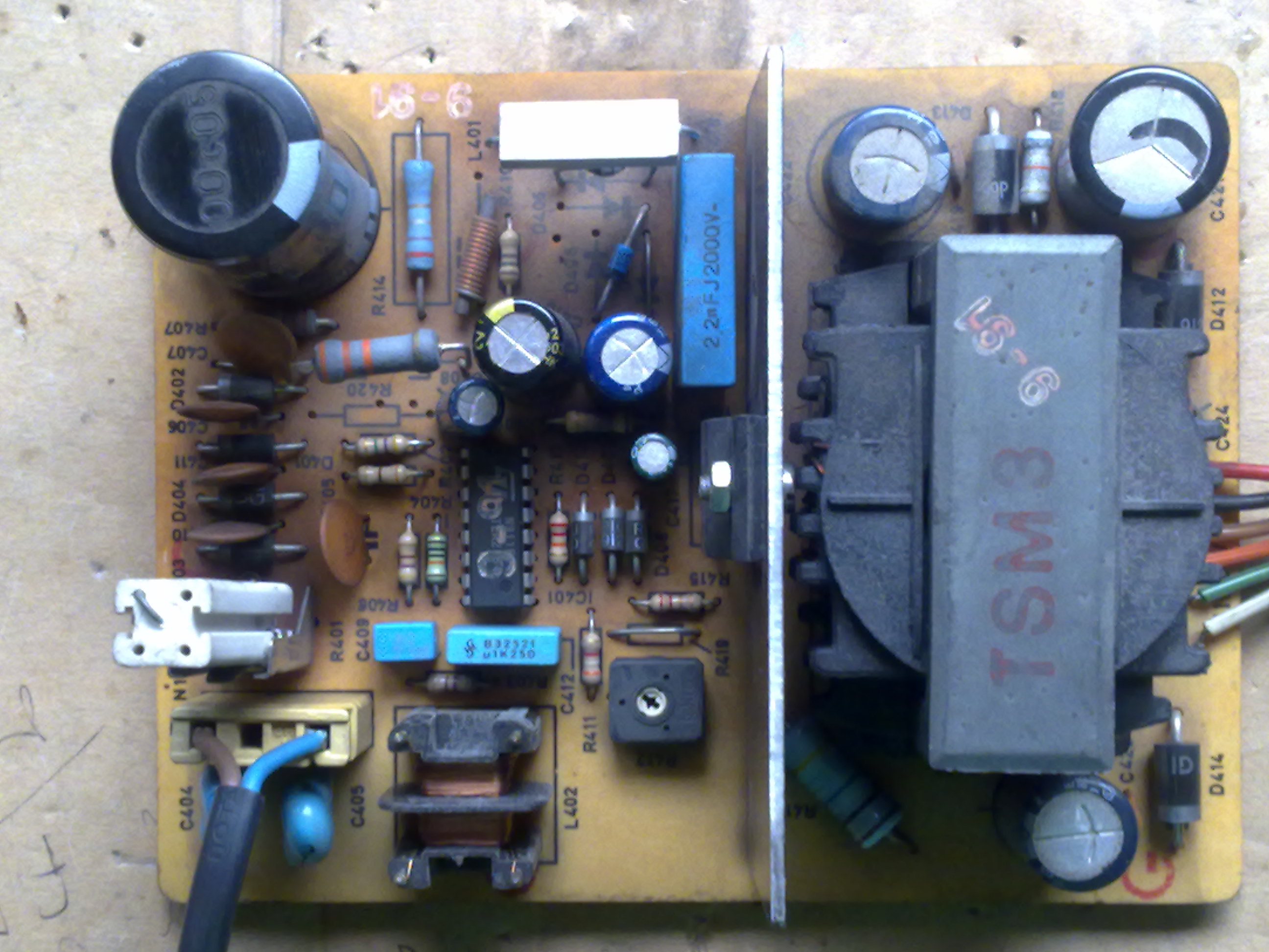
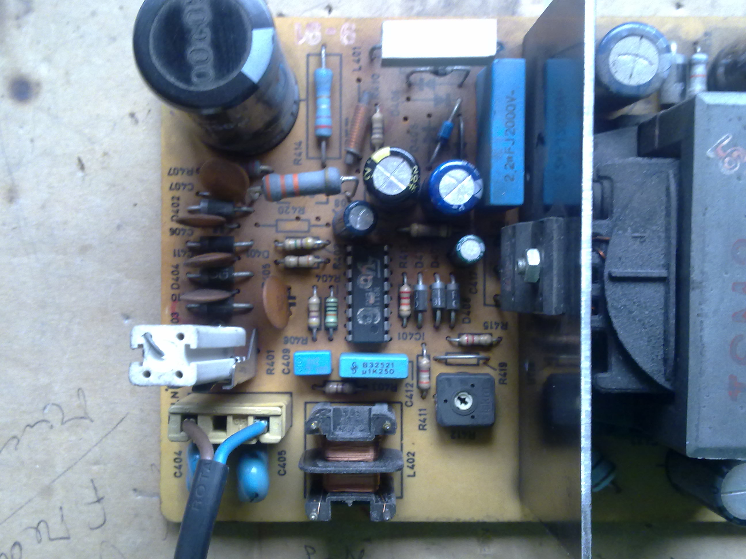
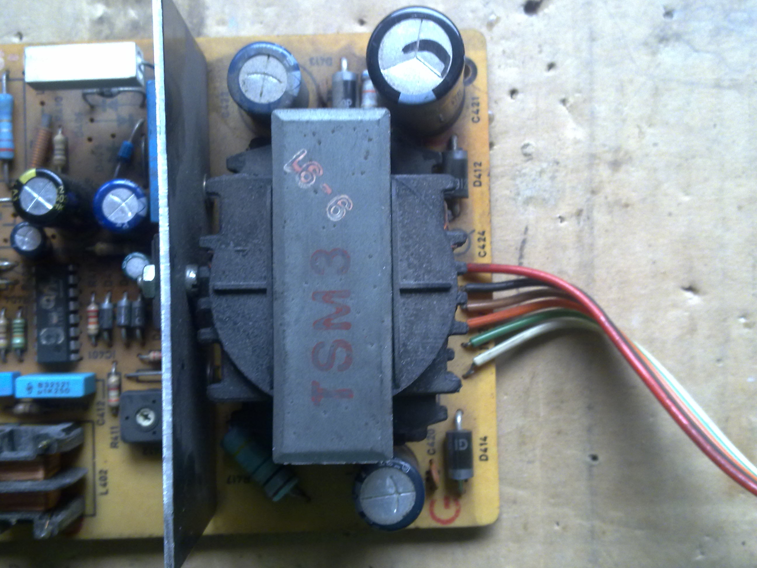
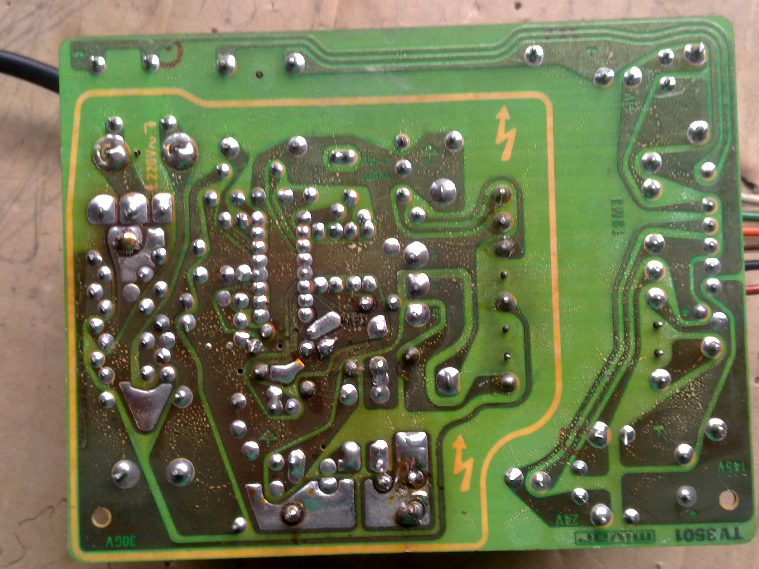
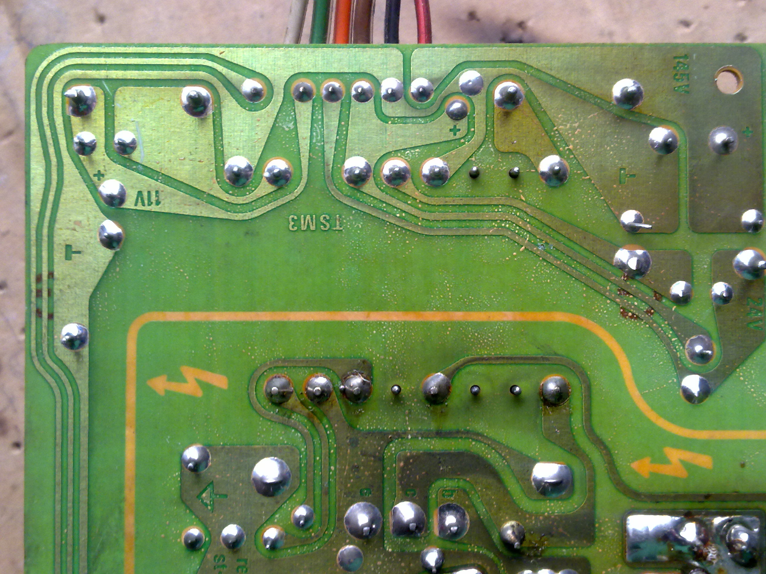
i would like to realize an power supply swicthing, using an "transformer" recovered from an old tv colour or pc monitor as that in the picture.
in output i will have need of 12 vdc and 1 ampere about.
i read some documents of the swicthing supply and i have seen that exist various type of this power supply.
if i understand good the first thing to do is
straighten the voltage ac in voltage dc with a brigde or four diode, after is need send this voltage to an "transformer", using an mosfet and an integrated circuit that pulse at high frequency.
i have seen that these transformer have two windings primary, and more windings secondary.
is possible to realize an power supply with these transformers
in the pictures there are two different transformers recovered from tv or pc monitor.
the side with four pin is primary winding on both transformers.
thank to you every for any help
best regards
erchiu
 

Well there is a couple of ways to do a switching power supply. There are also various calculators and circuit designers that do this for you but the general process is:
1.) Step down the AC voltage to a lower AC voltage
2.) Use an offline switcher to turn on/off the transformer
3.) Rectify the AC to DC
4.) Use a large ripple cap and filter to clean up the switching

So the switcher is driven by your signal and pulses the transformer. Most switchers have feedback and protection measures.

You can check continuity and resistance of the pins to find out what's connected. You would need an actual LC meter to find the inductance.
 

Nice thread in deed , but as far as i know in switching power supplys :

-AC libne voltage is first rectified then smoothed by high voltage electrolytic caps + other promary circuitry options , now this primary side voltage is switched on and off by a PWM module or an oscillator circuit using high frequency , this frequency is the rate of switching of the transformer in series with power transistors ....

But why high frequency is necessary ??
And how to choose the transformer after choosing the operating frequency and output current/voltage ?
 

ok, thank you for the answer.
looking the pcb where these transformers are mounted originally, i note always that the primary side have two separate winding, but i not understand as this must be connected.
i have seen that the ac voltage after the main switch accross an filter form two induttance (one for line), then passes through an rectifier bridge, after there is an capacitor of 400v and 68/100 uf.
I did not understand then what happens, i only understand that on primary side there is always an mosfet or power transistor and an IC for manage the pulsation.
i think that in some occasion, one component does all the work (IC control pwm and power transistor) , correct me if it's wrong.
i have an LC meter for measure the induttance, but i not understand how to move forward.
i have seen that some IC used for control of pwm signal are TEA2261 or TDA16846.
Can you help me to move forward?
thank you so much
regards erchiu
 

Without knowing more about these particular transformers it is pretty difficult to move forward. I'd suggest focusing on building the desired PSU rather than making these transformers a focal point.
 

thank you kam1787,
I would like to built an power supply and i thought of start to these transformers because i have been that are all very similar and this can help me for understand the operation of the circuit.
Looking always the section of power supply of old tv or pc monitor, i have been that after these transformer, there are always three value of voltage.
My idea was to use one of these voltage and learn something on these power supply type.
I would like understand well these circuits that today are in any appliance.
Thank to you for any help.
Regards erchiu
 

I suggest to review reference designs for an industry standard flyback switcher IC like UC3842. A simple circuit can be found in the datasheet.

You'll notice that one of the primary windings is an auxilary power supply. You should figure out a way to identify the windings ratio and polarity of all transformer windings, it's necessary for your design.
 

thank you FvM,
In this moment i can`t see the datasheet of this IC, but if i understand well, one winding is primary (connected to the mosfet) and one is auxilary (used for supply IC),
But please, Tell me is this wrong.
Thank you so much
Erchiu
 

Hi,
A switched-mode power supply is an electronic power supply that incorporates a switching regulator to convert electrical power efficiently. ...
 

thank you kam1787 for the link,
it's very interesting and is the a good start point.
in these days i found into my things one power supply of an old tv, separate from the main board.
there is the socket of input (220 vac) and a socket of output with 5 wires.
on the board (track side) there are the some voltage values indicated.
following the tracks i understood that each of these wire is an output:

red=145 vdc
blalck= ground
orange=24 vdc
green=11vdc
white=i don't know
brown= i don't know

i tryed to supply this board with the 220 vac but i have only the output between green wire and black wire and it's 11,9 vdc
because the is not the 24 vdc and there isn't the 145 vdc?
there is the white wire that i not understand good its function
maybe if is not connected to the rest of circuit the IC not issue the other output voltage, or is the power supply circuit has some problem?

i post some photos of this board

thank you so much everyone
regards
erchiu


maybe i understood.
The IC in use in this power supply is the TEA2164 and i have seen that it working with another IC the TEA2029 (placed on the main board), i think then working in master/slave way.
The question is this:
Is possible to change this configuation and to use only the IC 2164?
Regards and good weekend
Erchiu
 

Status
Not open for further replies.

Similar threads

Part and Inventory Search

Welcome to EDABoard.com

Sponsor

Back
Top