Continue to Site

Welcome to EDAboard.com

Welcome to our site! EDAboard.com is an international Electronics Discussion Forum focused on EDA software, circuits, schematics, books, theory, papers, asic, pld, 8051, DSP, Network, RF, Analog Design, PCB, Service Manuals... and a whole lot more! To participate you need to register. Registration is free. Click here to register now.

Surge stopper- fast gate turn off

Status
Not open for further replies.

Bobo_E

Newbie level 3
Joined
Jul 17, 2015
Messages
4
Helped
0
Reputation
0
Reaction score
0
Trophy points
1
Activity points
47
Hi

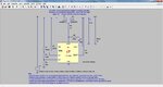
I am analysing a demo circuit for LTC4365. In the datasheet it says that in order to limit the inrush current a capacitor can be added to the gate pin. Then it also says to add a resistor to the gate pin so that the turn off time is not affected. I have done simulations with and without that resistor and it didn't make any difference. Could someone have a look at this and explain to me why there is the need for that Rgate resistor? Also does the connection order to the gate pin matter? ,ie. first Rgate (R6) and then Cgate (C2) (just like in the circuit) or can it be the other way round, ie. first Cgate and then Rgate?

LT Spice simulation is attached in the zip file.
 

Attachments

  • schematic.jpg
    schematic.jpg
    172 KB · Views: 96
  • LTC4365_TA02(1).zip
    1.3 KB · Views: 80
  • 4365fa.pdf
    495.8 KB · Views: 115

does the connection order to the gate pin matter?
Obviously not, according to resistor ratio.

I have done simulations with and without that resistor and it didn't make any difference.
There's no fast input voltage change in your simulation setup that would require fast turn-off.
 

What do you mean 'according to resistor ratio'?
There is a voltage change in the input voltage. From 12V to 2V. When the input gets below 3.5 V then the gate pin will be pulled low with a 50 mA sink current. Now from the datasheet:
'RGATE makes sure that CGATE does not affect the fast GATE turn off characteristics during UV/OV faults, or during reverse VIN connection.' So apparently the Rgate resistor is there for a purpose but in the simulation the graph for the turn off doesn't change at all, no matter whether the resistor is there or not. Could you explain this?
 

What do you mean 'according to resistor ratio'?
Calculate yourself if the position matters with 10 ohm/5.1 kohm.

Could you explain this?
The 10 nF is discharged with 50 mA, you don't see the resistor effect in your simulation.
 

I didn't mean the position of the resistors. I was asking whether connecting Cgate directly to the gate pin and then Rgate to the Cgate would make a difference (currently it is Rgate connected to the gate pin and then Cgate connected to Rgate). Accordingly to the simulation results there is no difference.

'The 10 nF is discharged with 50 mA, you don't see the resistor effect in your simulation.'

If I don't see the resistor effect in my simulation then is it because it has no effect, therefore, I could simply remove it from the circuit? If yes, then why in the datasheet they suggest to use Rgate (I know it says not to affect fast gate turn off but the simulation doesn't show any difference)? If no, then what would be the resistor effect in a practical circuit?
 

Status
Not open for further replies.

Similar threads

Part and Inventory Search

Welcome to EDABoard.com

Sponsor

Back
Top