Continue to Site

Welcome to EDAboard.com

Welcome to our site! EDAboard.com is an international Electronics Discussion Forum focused on EDA software, circuits, schematics, books, theory, papers, asic, pld, 8051, DSP, Network, RF, Analog Design, PCB, Service Manuals... and a whole lot more! To participate you need to register. Registration is free. Click here to register now.

Substrate definition in ADS EM simulation

Status
Not open for further replies.

R.Maher

Newbie
Joined
Jun 2, 2016
Messages
3
Helped
0
Reputation
0
Reaction score
0
Trophy points
1
Activity points
26
Hello everyone,
I try to design an RF rectifier using ADS co-simulation. I am confused about the correct definition of the substrate.
I need to define the back side of the substrate as the ground. what is the correct way?
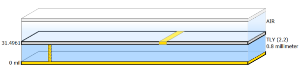
I defined two copper layers (on top and bottom of the dielectric), draw my layout on the top layer, draw a rectangular shape on the back side, and define this back conductor as the ground for the input port.
I used TML calibration for this input pin port only.

Are these steps correct to match measurements?
Also If get negative real impedance from the layout EM simulation (before connecting lumped elements for co-simulation),
What does this mean?

Thank you all and waiting for your help.

port setup.png
 

Solution
Yes, my layout is single sided so I will work with your answer. But if I want to draw a defected ground structure, how to define the substrate?

In that case, your approach above would be fine. Just make sure that your port references have some connection (same as in real world), so that current can flow.

Switch off port calibration in that case, this should solve your unphysical result issue.
Be careful with port grounds: current can only flow in closed loops. If your DC load uses another port ground conductor than the RF input port, simulation will fail.

If your layout is essentially single sided, with all the backside as one large ground, you can use an infinite ground boundary in Momentum stackup (see pictue). That is recognized by Momentum as the default (implicit) ground reference for all ports.

Regarding port calibration, TML seems to fail on your port 1. Most likely that is because you have specified cond2 for ground and there is no cond2 ground drawn below the calibration line. For this explicit (drawn) ground layer, I would switch off TML port cal. If you use the infinite ground boundary instead, TML cal should work fine.
 

Attachments

  • emsub.png
    emsub.png
    7.1 KB · Views: 121

Be careful with port grounds: current can only flow in closed loops. If your DC load uses another port ground conductor than the RF input port, simulation will fail.

If your layout is essentially single sided, with all the backside as one large ground, you can use an infinite ground boundary in Momentum stackup (see pictue). That is recognized by Momentum as the default (implicit) ground reference for all ports.

Regarding port calibration, TML seems to fail on your port 1. Most likely that is because you have specified cond2 for ground and there is no cond2 ground drawn below the calibration line. For this explicit (drawn) ground layer, I would switch off TML port cal. If you use the infinite ground boundary instead, TML cal should work fine.
Thank you for your help and explanation.

essentially single sided, with all the backside as one large ground
Yes, my layout is single sided so I will work with your answer. But if I want to draw a defected ground structure, how to define the substrate?

The reference point for the RF input is under the input line. For the DC load, there is a via to the ground layer and it is the DC ground reference.
 

Yes, my layout is single sided so I will work with your answer. But if I want to draw a defected ground structure, how to define the substrate?

In that case, your approach above would be fine. Just make sure that your port references have some connection (same as in real world), so that current can flow.

Switch off port calibration in that case, this should solve your unphysical result issue.
 

Solution
Status
Not open for further replies.

Part and Inventory Search

Welcome to EDABoard.com

Sponsor

Back
Top