metiz
Junior Member level 1

- Joined
- Aug 5, 2010
- Messages
- 15
- Helped
- 0
- Reputation
- 0
- Reaction score
- 0
- Trophy points
- 1,281
- Location
- hhd
- Activity points
- 1,401
Hi,
I'm working on a project where I have to get a weight readout from a straingage attached to an aluminium box profile. The mechanical part of the assignment is done, but they're realy letting us hanging with the electronics part.
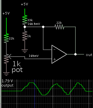
We were handed this circuit scematic (after specifically asking a teacher not involved in the project).

Some mods have been made after advice from other students: Removed the diode, replaced the 390 ohm resistor on the right with a 10K one, replaced the direct-to-ground lead from pin 5 with a 1M ohm resistor. "rekstrookje" means straingage btw (I'm dutch). the straingage is not yet attached, I use a potentiometer.
I'm using an arduino uno with Basic Firmata and Firmata Test to see if I get any signal on ports A0 through A5. Regardless of POT setting, I get a reading between 1000 and 1020. If I hook up to, for example, A3 then it too will show 1000, as well as A4 to A6.
We BARELY have done anything with an arduino, we just sratched the surface of OP AMPS and have basically zero programming experience. The assignment basically says "Figure it out"
Is this circuit usable and if not, how do I change it;
How can I imput the data to an arduino and get an actual weight readout with TARE and ZERO "buttons"? (Since we're expected to "figure it out", I'm all up for a ready-made Github program);
Are there easier ways to do this? an Arduino is not required per-sé
A final thought: If I buy a 2nd hand kitchen scale and hook up our straingage to it, then use an arduino to compensate for whatever deviation in the readout we're getting, would that work?
Thanks,
Joost.
I'm working on a project where I have to get a weight readout from a straingage attached to an aluminium box profile. The mechanical part of the assignment is done, but they're realy letting us hanging with the electronics part.
We were handed this circuit scematic (after specifically asking a teacher not involved in the project).
Some mods have been made after advice from other students: Removed the diode, replaced the 390 ohm resistor on the right with a 10K one, replaced the direct-to-ground lead from pin 5 with a 1M ohm resistor. "rekstrookje" means straingage btw (I'm dutch). the straingage is not yet attached, I use a potentiometer.
I'm using an arduino uno with Basic Firmata and Firmata Test to see if I get any signal on ports A0 through A5. Regardless of POT setting, I get a reading between 1000 and 1020. If I hook up to, for example, A3 then it too will show 1000, as well as A4 to A6.
We BARELY have done anything with an arduino, we just sratched the surface of OP AMPS and have basically zero programming experience. The assignment basically says "Figure it out"
Is this circuit usable and if not, how do I change it;
How can I imput the data to an arduino and get an actual weight readout with TARE and ZERO "buttons"? (Since we're expected to "figure it out", I'm all up for a ready-made Github program);
Are there easier ways to do this? an Arduino is not required per-sé
A final thought: If I buy a 2nd hand kitchen scale and hook up our straingage to it, then use an arduino to compensate for whatever deviation in the readout we're getting, would that work?
Thanks,
Joost.