Continue to Site

Welcome to EDAboard.com

Welcome to our site! EDAboard.com is an international Electronics Discussion Forum focused on EDA software, circuits, schematics, books, theory, papers, asic, pld, 8051, DSP, Network, RF, Analog Design, PCB, Service Manuals... and a whole lot more! To participate you need to register. Registration is free. Click here to register now.

[SOLVED] Stepper motor driving not working

Status
Not open for further replies.

varunme

Advanced Member level 3
Joined
Aug 10, 2011
Messages
741
Helped
17
Reputation
36
Reaction score
17
Trophy points
1,318
Activity points
5,764
my code

************************************************************************************
stepper.c
#include <htc.h>


__CONFIG( HS & UNPROTECT & BORDIS & PWRTDIS & WDTDIS );


// Main function
void main(void) {

TRISB=0;
PORTB=0;

/*
INTCON = 0x0; // Disable inerupt
CMCON = 0x07; // Comparators Off
ADCON1 = 0x06; // Port as Digital IO
CCP1CON = 0; // P1B, P1C, P1D assigned as port pins


TRISC=0;
PORTC=0;

*/

// loop forever - echo
while(1) {


PORTB=0b00000001;
_delay(250);
PORTB=0b00000010;
_delay(250);
PORTB=0b00000100;
_delay(250);
PORTB=0b00001000;
_delay(250);


}
}

**************************************************************


not working , what can be the reason ?

it works in proteus but in real world with LED itsn't working
 

Post your schematic so we can see what you are trying to do

Alex

P.S. I have moved your post here because you have posted the message in a threads unrelated to microcontrollers.
 

What model PIC are you using in your design?

If you look in the appropriate device header file, e.g. pic16f877a.h, you will see the correct configuration mask definitions for use with _CONFIG():

Code:
#ifndef	_HTC_H_
#warning Header file pic16f877a.h included directly. Use #include <htc.h> instead.
#endif

/* header file for the MICROCHIP PIC microcontroller
 *  16F877A
 */


#ifndef __PIC16F877A_H
#define __PIC16F877A_H

//
// Configuration mask definitions
//


// Config Register: CONFIG
#define CONFIG               0x2007
// Oscillator Selection bits
// RC oscillator
#define FOSC_EXTRC           0xFFFF
// HS oscillator
#define FOSC_HS              0xFFFE
// XT oscillator
#define FOSC_XT              0xFFFD
// LP oscillator
#define FOSC_LP              0xFFFC
// Watchdog Timer Enable bit
// WDT enabled
#define WDTE_ON              0xFFFF
// WDT disabled
#define WDTE_OFF             0xFFFB
// Power-up Timer Enable bit
// PWRT disabled
#define PWRTE_OFF            0xFFFF
// PWRT enabled
#define PWRTE_ON             0xFFF7
// Brown-out Reset Enable bit
// BOR enabled
#define BOREN_ON             0xFFFF
// BOR disabled
#define BOREN_OFF            0xFFBF
// Low-Voltage (Single-Supply) In-Circuit Serial Programming Enable bit
// RB3/PGM pin has PGM function; low-voltage programming enabled
#define LVP_ON               0xFFFF
// RB3 is digital I/O, HV on MCLR must be used for programming
#define LVP_OFF              0xFF7F
// Data EEPROM Memory Code Protection bit
// Data EEPROM code protection off
#define CPD_OFF              0xFFFF
// Data EEPROM code-protected
#define CPD_ON               0xFEFF
// Flash Program Memory Write Enable bits
// Write protection off; all program memory may be written to by EECON control
#define WRT_OFF              0xFFFF
// 0000h to 00FFh write-protected; 0100h to 1FFFh may be written to by EECON control
#define WRT_256              0xFDFF
// 0000h to 07FFh write-protected; 0800h to 1FFFh may be written to by EECON control
#define WRT_1FOURTH          0xFBFF
// 0000h to 0FFFh write-protected; 1000h to 1FFFh may be written to by EECON control
#define WRT_HALF             0xF9FF
// In-Circuit Debugger Mode bit
// In-Circuit Debugger disabled, RB6 and RB7 are general purpose I/O pins
#define DEBUG_OFF            0xFFFF
// In-Circuit Debugger enabled, RB6 and RB7 are dedicated to the debugger
#define DEBUG_ON             0xF7FF
// Flash Program Memory Code Protection bit
// Code protection off
#define CP_OFF               0xFFFF
// All program memory code-protected
#define CP_ON                0xDFFF

...
...

Device specific headers can be located in the following directory:

C:\Program Files\HI-TECH Software\PICC\9.81\include

You will notice these definitions do not resemble the definitions you have used in the _CONFIG() statement.

Also, what is the clock frequency of the device?

BigDog
 

thank you bigdogguru,
I am using 16F72
 

There are definitely significant differences between the definitions in the pic16f72.h file and those you have used in the _CONFIG(), unfortunately the Hi-Tech C compiler does not issue a warning or error with the use of improper defines in the _CONFIG() statement.

Reference pic16f72.h:

Code:
//
// Configuration mask definitions
//


// Config Register: CONFIG
#define CONFIG               0x2007
// Oscillator Selection bits
// RC oscillator
#define FOSC_RC              0xFFFF
// HS oscillator
#define FOSC_HS              0xFFFE
// XT oscillator
#define FOSC_XT              0xFFFD
// LP oscillator
#define FOSC_LP              0xFFFC
// Watchdog Timer Enable bit
// WDT enabled
#define WDTE_ON              0xFFFF
// WDT disabled
#define WDTE_OFF             0xFFFB
// Power-up Timer Enable bit
// PWRT disabled
#define PWRTE_OFF            0xFFFF
// PWRT enabled
#define PWRTE_ON             0xFFF7
// FLASH Program Memory Code Protection bit
// Code protection off
#define CP_OFF               0xFFFF
// All Memory locations code protected
#define CP_ON                0xFFEF
// Brown-out Reset Enable bit
// BOR enabled
#define BOREN_ON             0xFFFF
// BOR disabled
#define BOREN_OFF            0xFFBF

The watchdog timer might be the culprit if not disable correctly, as well as the oscillator module.

I usually add the appropriate device specific header file to the project window, so that I can reference it while coding.

Make the appropriate changes to the Configuration Bit Mask Definitions and post your results.

BigDog
 

but in my PC its something like this

#ifndef _HTC_H_
#warning Header file pic16f7x.h included directly. Use #include <htc.h> instead.
#endif

/*
* Header file for the Microchip
* PIC 16F72 chip
* PIC 16F73 chip
* PIC 16F74 chip
* PIC 16F76 chip
* PIC 16F77 chip
* Midrange Microcontroller
*/

/*osc configurations*/
#define RC 0x3FFF // resistor/capacitor
#define HS 0x3FFE // high speed crystal/resonator
#define XT 0x3FFD // crystal/resonator
#define LP 0x3FFC // low power crystal/resonator

/*watchdog*/
#define WDTEN 0x3FFF // watchdog timer enable
#define WDTDIS 0x3FFB // watchdog timer disable

/*power up timer*/
#define PWRTEN 0x3FF7 // power up timer enable
#define PWRTDIS 0x3FFF // power up timer disable

/*brown out reset*/
#define BOREN 0x3FFF // brown out reset enable
#define BORDIS 0x3FBF // brown out reset disable

/*code protection*/
#define UNPROTECT 0x3FFF // do not protect the code
#define PROTECT 0x3FEF // protect the program code
 

You should always use the device header file that is installed with your compiler, so your configuration bit settings appear to be correct in this case.

What version of the Hi-Tech C Compiler is installed in your system? Version 9.70? It might be time to update your compiler.

Can you post the schematics as Alex suggested?

Also what oscillator frequency are you running?

What is the stepper motor model? What type of driver circuit are you using?

BigDog
 

Hi

you just cross check once that r u giving
proper step sequency or not because it is depending on
motor you used liku ur using bipolar or unipolar motor and check with time delay also
defenitely you will get that work.
 

I am using hitech C 9.80 for PIC 16,18 ..
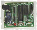
The board i am using is
pod4_rq7_p0639_05.png
Its using ULN2803 as the driver chip
Port B is connected to the driver
The Stepper I am using is EPOCH T1319635 , five wire unipolar.
The real problem i think is with the program , because , the LED just lights up and not blinking when connected to RB0, RB1, RB2, RB3
Oscilltor frequency is 5MHz
 

Actually, I believe the crystal is 4MHz.

A oscillator frequency of 4MHz equates to an instruction cycle of 1uS, therefore those _delay(250) statements represent a delay of only 250uS which generates a refresh rate of faster than the eye can detect even a flicker. Therefore the LEDs will appear to be constantly ON. You may want to use the _delay_ms() library function instead, however be sure and define __XTAL_FREQ.

The delays should be more in the range of milliseconds, rather than a few hundred microseconds.
It appears you are also driving the stepper at only a half step rather than a full step.

Here are a few example programs, which you should be able to adapt to your dev board:

PIC Stepper Motor Controller

Stepper Motor controller

**broken link removed**
Stepper Motor Controller"]Stepper Motor Controller

BigDog
 
Last edited by a moderator:

yes its 4MHz , sorry
 

yes, finally I got it working
it was the delay problem
thank you very much bigguru
 

Now that you've got it working, you may want to try driving the stepper using a full step rather than a half step.

BigDog
 

Yes , for that I have to energize two coils isnt it ?
like
1010
1001
0101
0110
isnt it ?
 

Status
Not open for further replies.

Part and Inventory Search

Welcome to EDABoard.com

Sponsor

Back
Top