Vermes
Advanced Member level 4
The application is based on project J31 from Jabel with redesigned board (for most currents). The power supply can give larger voltage, provided that you supply the operational amplifier LM324 by the stabilizer – so that the maximum voltage was 32V.
Rectifier bridge can be home made. The meter is powered from a separate power supply, which does not have a galvanic connection with proper power supply. The power supply has also derived 12V alternating voltage directly from the transformer (terminals are next to the main switch).
It seems that the fan is not needed for such a large heat sink.
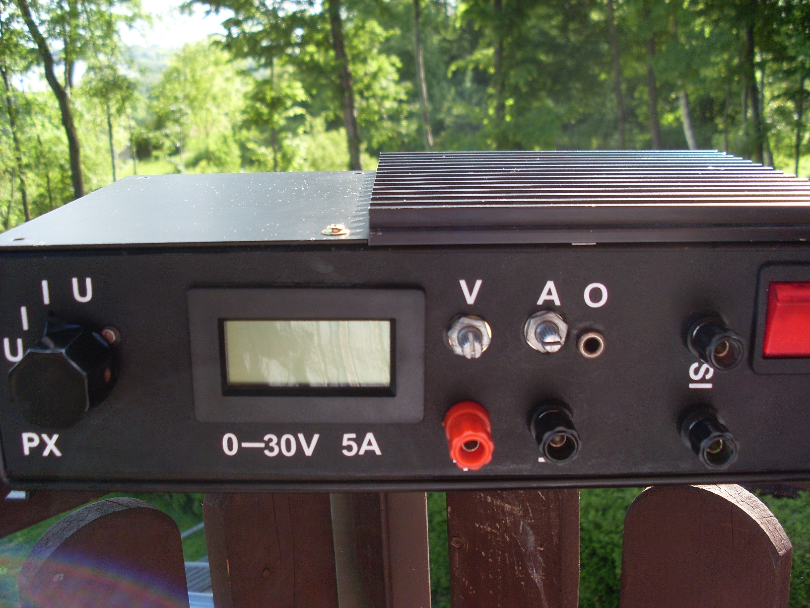
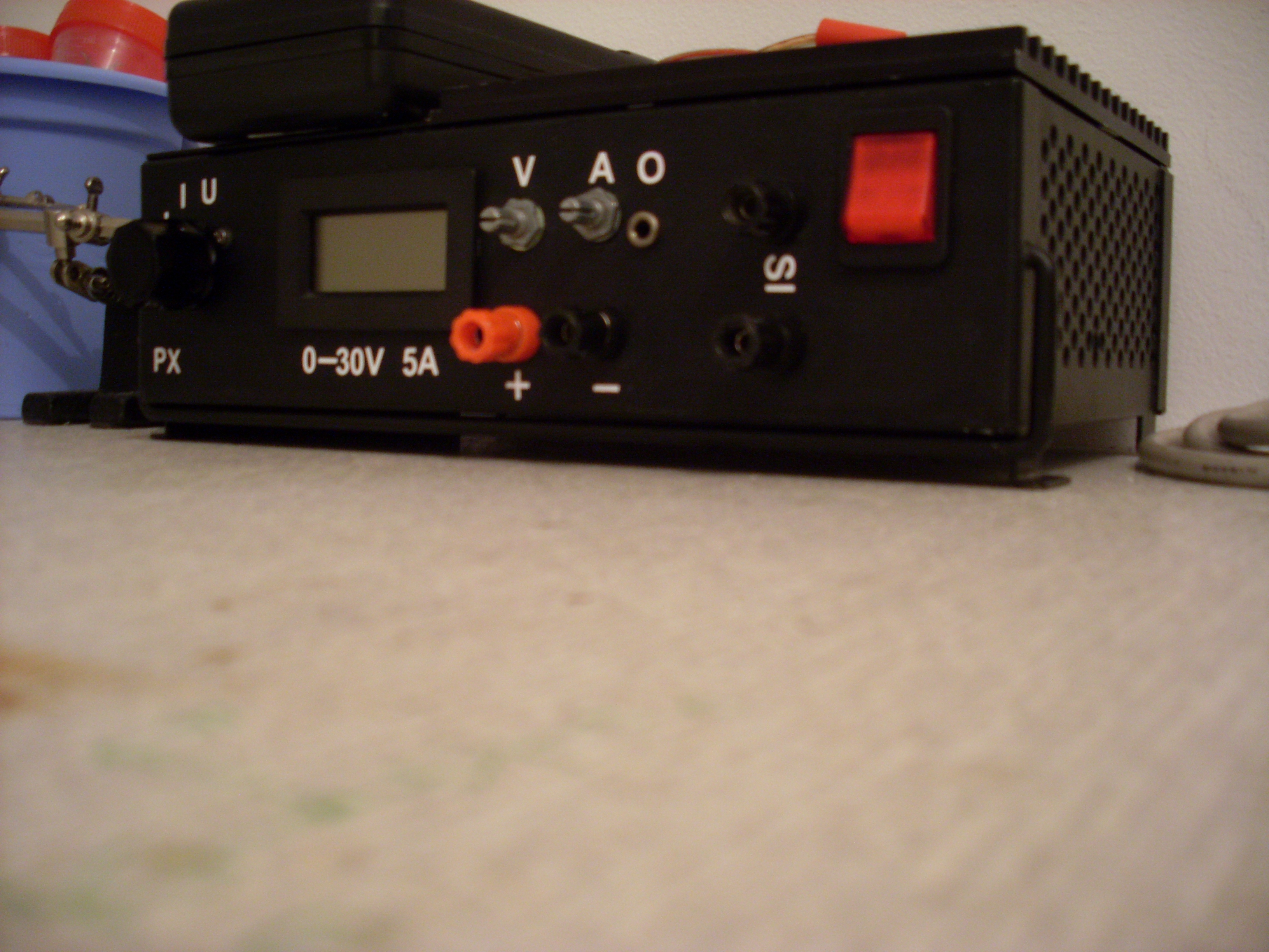
Voltmeter operates in four ranges:
- U – voltage measurement to 200V
- I – current measurement to 2A
- I – current measurement to 20A
- U – voltage measurement to 20V
Elements that were changes (J31):
- transformer: 200W, 2x 12V
- rectifier bridge: rectifying diodes 4x 5A
- filtering: 10000uF 50V
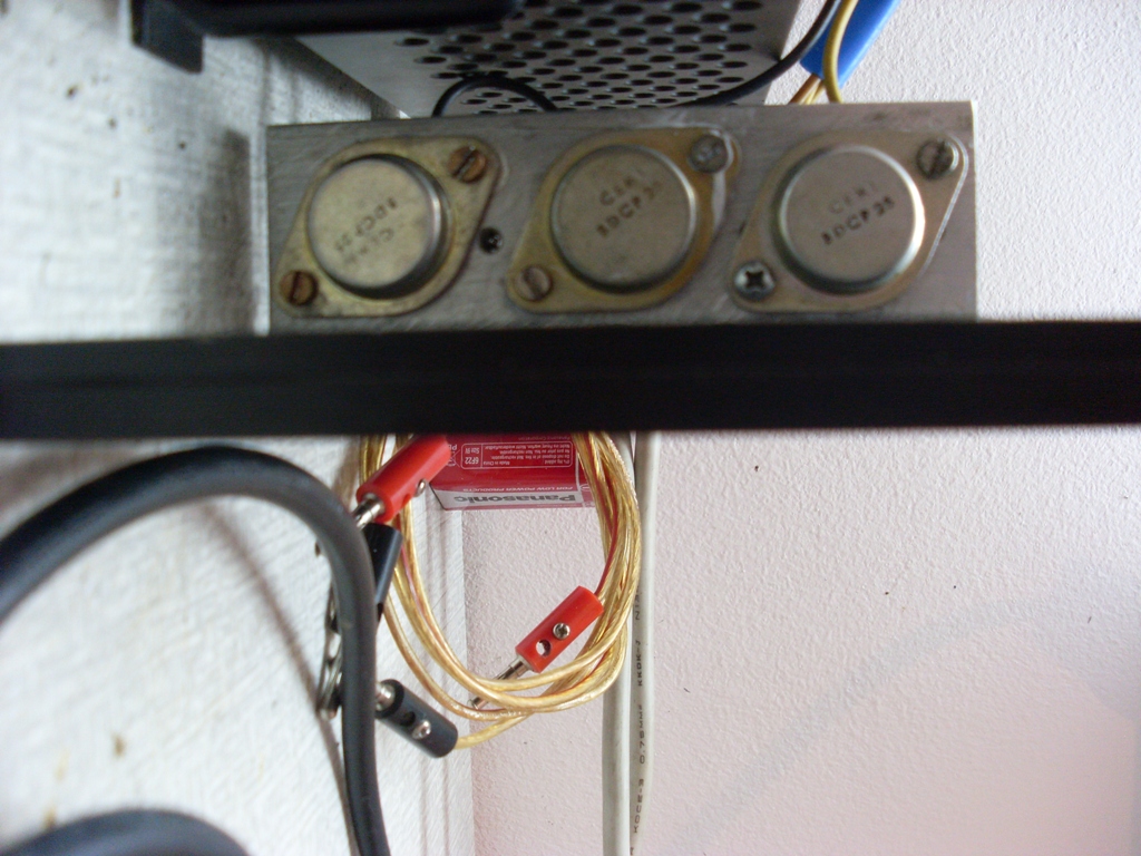
- power transistors: BDCP 25 x 3 (+ compensatory resistors in emitters 0,1ohm 5W)
- resistor R14: 0,1ohm 10W
- Zener diode: 6V2
1,2ohm resistor got: 5,6A 28V
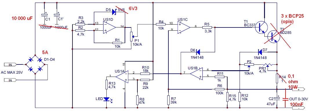
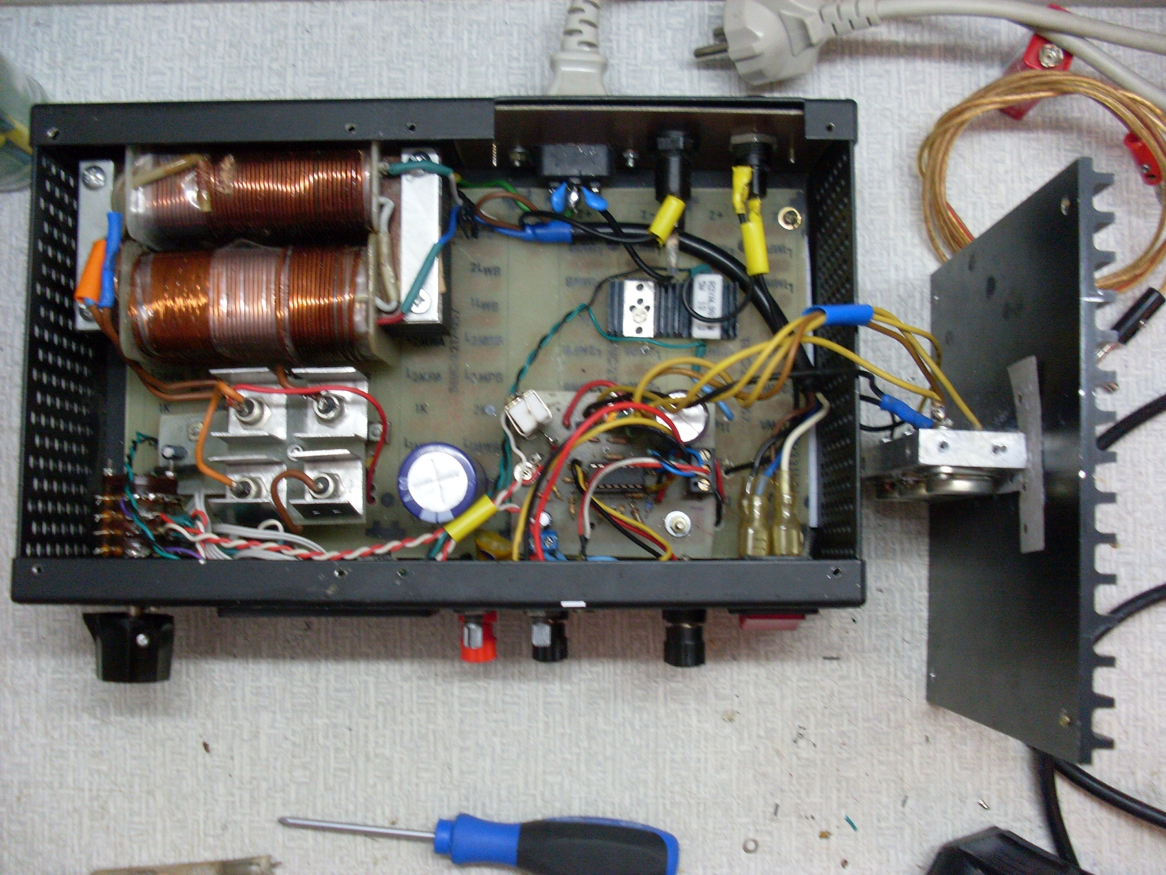
Schematic diagram with modifications:
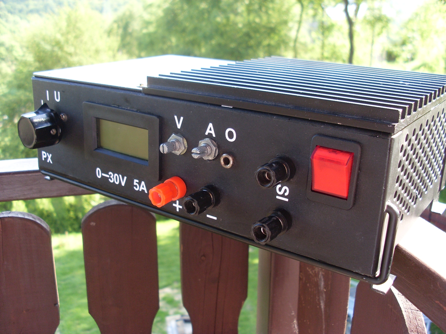
Pictures:
Link to original thread (useful attachment) – Zasilacz stabilizowany 0...30V, 5A