Continue to Site

Welcome to EDAboard.com

Welcome to our site! EDAboard.com is an international Electronics Discussion Forum focused on EDA software, circuits, schematics, books, theory, papers, asic, pld, 8051, DSP, Network, RF, Analog Design, PCB, Service Manuals... and a whole lot more! To participate you need to register. Registration is free. Click here to register now.

Stability of in bridge working amplifiers

Status
Not open for further replies.

TomasPitak

Newbie level 3
Joined
Nov 5, 2009
Messages
4
Helped
0
Reputation
0
Reaction score
0
Trophy points
1,281
Location
Slovakia
Activity points
1,313
Hi,
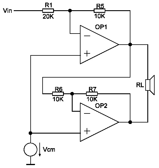
how to test stability of bridged amplifiers?

Normally I'm using Middlebrook's method but I can't use it to test attached circuit. I can test only each amplifier. From one previous project I know that stability of this circuit is worst then of one voltage follower connected operational amplifier.
Any ideas? Thanks.


Hi Tomas,

if the amplifiers in your circuit are really opamps (as indicated) and if one assumes that their output impedances are sufficient low, the load RL does not influence the operation at all.
In this case, you simply have two inverting opamp circuits in series without overall feedback.
Therefore, you can do a stability test for each opamp separately.
The result may be different for finite output opamp impedances and for a load that is not resistive (in contrast to your load denoted as RL).
By the way - where do you see a bridge topology?
 

Stability analysis of a multi-loop feedback system is ususally achieved by testing the outer loop. The present circuit however consists of two independant feedback loops. At first look, they seem unlinked, so it would be sufficient to perform individual stability analysis for both loops.

Actually, considering the properties of a real OP, the OP output resistance creates a coupling between both loops and it's also the reason why the stability of the complete cicrcuit may be somewhat worse - for low RL values. But then you'll see respective stability issues in the loop gain of both loops.
 

Thanks for reply.

In my case this two amplifier are class-AB amplifiers driving load of 8 Ω resistor and 300p capacitor. Amplifiers are the same. And they are stable in voltage follower configuration. But from previous project I know that there are big stability problems with low load. Therefore I am searching for some method how to test whole circuit.
I am using bridged configuration to increase power of amplifier. But mayby fully differential amplifier is better solution for this problem.
 

TomasPitak said:
.................
I am using bridged configuration to increase power of amplifier. .

It's perhaps not very important - but I repeat: I see no bridge topology.
(For my opinion, a bridge consists of two chains which are fed by a common signal source; in your circuit I only see one input terminal).

Regarding stability: If you are interested only in an answer yes/not I think a tran analysis (step response) with evaluation of the overshoot would suffice.
If you like to know some kind of margin it is somewhat complicated because there is not only one dominant loop (mostly, as mentioned by FvM, this is the outer loop). At least it is not possible by visual inspection to identify such a loop.
On the other side, the principle of stability margin is somewhat questionable in a multiloop system, because it is not easy to answer the question: Which margin of which loop should be considered as dominant?
For my opinion, this question still is not yet answered or - perhaps this is the right answer: It is not allowed (or not relevant) to ask such a question because the concept of stability margin was developed only for single loop systems resp. for systems exhibiting a dominant outer loop.
 

I think it is bridged cofiguration. One output is positive and one negative. But its not done in a way with one inverting OPAMP and one non inverting OPAMP. Here are two amplifiers in inverting configuration where on output of first one is signal shift on 180° (negative output) and on second one on 360° (positive output). And according to stability I was searching for some phase margin plot but you are right it's only for single loop sytem.
 

I think, the load is actually connected in a bridge configuration. Besides LvW's exact explanation of the stability situation,
it can be expected that the loop gain of both feedback loops in the present circuit reveals existing stability issues. So
there's no practical problem.

You already considered to drive both amplifier inputs in parallel. Besides effects on stability, expectable lower overall
distortions can be a sufficient motivation to do so.
 

Status
Not open for further replies.

Similar threads

Part and Inventory Search

Welcome to EDABoard.com

Sponsor

Back
Top