sina shekari
Newbie level 4
Please I need help on speed control of 3phase motor using thyristor.
Whit these Descriptions:
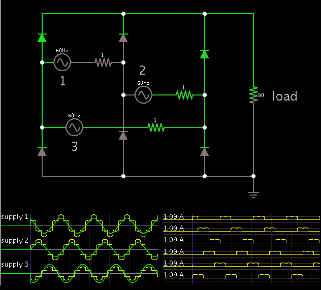
Three Phase Fully Contolled Bridge Rectifier (6 Thyristors)
Change the firing angle using 6-pulse generator.
Voltmeter is used for measuring phase voltages.
Multimeter1 is used for measuring voltages across all the 6 thyristors.
Whit these Descriptions:
Three Phase Fully Contolled Bridge Rectifier (6 Thyristors)
Change the firing angle using 6-pulse generator.
Voltmeter is used for measuring phase voltages.
Multimeter1 is used for measuring voltages across all the 6 thyristors.