Continue to Site

Welcome to EDAboard.com

Welcome to our site! EDAboard.com is an international Electronics Discussion Forum focused on EDA software, circuits, schematics, books, theory, papers, asic, pld, 8051, DSP, Network, RF, Analog Design, PCB, Service Manuals... and a whole lot more! To participate you need to register. Registration is free. Click here to register now.

Speed Control Of DC motor using 3phase fully controlled bridge converter

Status
Not open for further replies.

sina shekari

Newbie level 4
Newbie level 4
Joined
Nov 21, 2013
Messages
6
Helped
0
Reputation
0
Reaction score
0
Trophy points
1
Visit site
Activity points
36
Please I need help on speed control of 3phase motor using thyristor.
Whit these Descriptions:

Three Phase Fully Contolled Bridge Rectifier (6 Thyristors)
Change the firing angle using 6-pulse generator.
Voltmeter is used for measuring phase voltages.
Multimeter1 is used for measuring voltages across all the 6 thyristors.

Speed Control Of DC motor using 3phase fully controlled bridge converter


Hi Sina
First of all i need to say that name of your thread and the question which is inside are different . why ?
You said speed control of DC motor and then you have asked for a three phase motor control via thyristor !

I suspect it is some sort of final project isn't it ? and i hope you are not expecting that someone give you all of the things specially red paragraph in a map and you just build it !!!!

Anyway . i can guide you to design it . first mention the required power ( current and voltage ) and type of your nominal load . and ask what is your exact problem , then i'll guide you . furthermore , why SCR ? why not IGBT instead which can be much better here ?

Best Wishes
Goldsmith
 

i creat simulation but i don't know why my answers is not correct
speed image wave is not correct
i have attached my simulation
Screen Shot 2013-11-22 at 10.44.34 PM.pngScreen Shot 2013-11-22 at 10.44.00 PM.png
 

Looking closely at the bottom-right terminals on T2, T4, T6...

They are connected to each other, but not to anything else.

You may have noticed already that if you try to ground those terminals, you get a short circuit.
 

Looking closely at the bottom-right terminals on T2, T4, T6...

They are connected to each other, but not to anything else.

You may have noticed already that if you try to ground those terminals, you get a short circuit.
i want to simulate shunt dc motor but i don't know how change the dc machine in matlab to shunt dc motor!!
i put ground as you told but the result didn't change!!
Screen Shot 2013-11-23 at 3.39.50 PM.pngScreen Shot 2013-11-23 at 3.40.13 PM.png
 

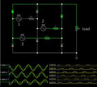
This is the only arrangement which I can get to work with a 6 diode bridge (in simulation that is).


There is no short circuit (as shown by the scope traces). All six diodes get identical current.

It may not be easy to adapt thyristors to the above layout.
 

i think this site have lot of expert in power electronic but i find out most of them are amateur...
finally i myself find the problem and solve it.
some so-called expert thinking that it's my final project and i can not do it!
 

Status
Not open for further replies.

Similar threads

Part and Inventory Search

Welcome to EDABoard.com

Sponsor

Back
Top