Continue to Site

Welcome to EDAboard.com

Welcome to our site! EDAboard.com is an international Electronics Discussion Forum focused on EDA software, circuits, schematics, books, theory, papers, asic, pld, 8051, DSP, Network, RF, Analog Design, PCB, Service Manuals... and a whole lot more! To participate you need to register. Registration is free. Click here to register now.

SOT223 with 1.1W dissipation and gap pad to its plastic case top?

cupoftea

Advanced Member level 5
Joined
Jun 13, 2021
Messages
2,611
Helped
54
Reputation
108
Reaction score
115
Trophy points
63
Activity points
13,685
Hi,
A customer has sent us a product PCB to modify....

We have eight linear regulators, using SOT223 BJTs (PBSS4540).
Vin=20V
Vout = 2V
Load is 64mA.
(There's a current clamp aswell, but no need to go into it)
So the SOT223 dissipates 1.1W.
Trouble is, there are eight of these linear regs, and the eight SOT223's are "shoulder to shoulder" on the PCB. (no other room).
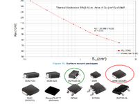
PCB copper is 1oz. The area directly under each SOT223 has a copper pour, so the total copper pour area is 22mm^2.
Board is 4 layer but there is no room for a bottom copper pour, or any intermediary layer copper pour.

The eight SOT223's are gap-padded to the heatsink below.
The gap pad is just big enough to cover the eight SOT223's
The gap pad is filling the 3.2mm gap between the plastic top of the SOT223's and the heatsink.

In a thermal test, with all eight regulators fully loaded (1.1W dissipation in each SOT223), i measured with thermocouple, 75degC at the case of each SOT223.
This was in 20degC ambient. (Kit must operate to 40degC ambient.)

The thing is, the TLV1117 datasheet from ti.com, on page 4, states that SOT223 has 54 degC/Watt for Rth(J-case top).

So that means, our SOT223 junctions will be 126 degC when ambient is 20degC....but will be 146degC when ambient is 40degC.

This is obviously too hot.

Woudl you agree, it is not acceptable to operate any SOT223 above 110degC junction? (150degC is abs max, but we all know that any operation
above 110degC means premature failures
through expansion/contraction problems in the SOT223 package.

And do you agree with the 54 degC/Watt Rth(j-case Top) for SOT223?

TLV1117 page 4 gives Rth(j-case top) for SOT223 (DCY package)
 
Thanks, yes i see your point, they want a quick fix with as few as poss changes, but i think youre right.
Unfortunately we cant have fans.
The product is in a large enclosure (with a lot of other stuff) which does have vent holes.

May i ask do you agree with 54degC /Watt for Rth(j-case Top) for SOT223?
 
* Can you re-arrange for any load to have its own current path? Give the load a 20V source on one end, an 18V source on the opposite end, for a net voltage of 2V?

* Can you stack two or more loads in a series string? Two loads in series could accept 4V, thus giving each load 2V. Your 20V supply could accommodate 10 loads in series. This might require that you give rewire loads if they need a separate ground.
 
For Silicon, in order to prevent a failure, in otherwords having a reasonable MTBF, the Junction temperature shouldn't exceed +85 degree.
If I were you, I'd use DPAK Case instead of SOT-223.
 
Thanks, do you know the Rth(j-case top) for DPAK? (and/or SOT223)?
Does anyone know Rth(j-case top) for any SMD device wth plastic case top?
These things simply arent stated anywhere on the web.
 
Thanks but your kindly given doc doesnt show Rth(j-case top) for any SMD device wth plastic case top.
Ayk thru case top is not the accepted method by semico's , so they dont tell this...even though its a majorly popular way in the actual world.
 
Thanks but your kindly given doc doesnt show Rth(j-case top) for any SMD device wth plastic case top.
Ayk thru case top is not the accepted method by semico's , so they dont tell this...even though its a majorly popular way in the actual world.
Really? Yes it does. and shows effect of Cu area. I can estimate just from ratio of Cu to Epoxy area on SMD Understand the assumptions for these plots.,
1704481005376.png

1704481053690.png


1704480965171.png

--- Updated ---

Quick fix is a cut and jumper to 250 ohm 2W resistor axial raised away from parts 50'C rise.
Thermal Ohm's Law is trivial.

 
Last edited:
Thanks but we cant use a resistor, as sometimes we need different voltage output.
Also, From the above it seems to suggest that its possible to estimate Rth(j-case Top) from the value of
Rth(ja) and a knowledge of the Cu area of the a-joined Cu pad on the PCB.
Though i am not certain how that follows.
 
May i ask do you agree with 54degC /Watt for Rth(j-case Top) for SOT223?
The datasheet looks trustworthy.
Also, From the above it seems to suggest that its possible to estimate Rth(j-case Top) from the value of
Rth(ja) and a knowledge of the Cu area of the a-joined Cu pad on the PCB.
Not without taking other parameters into consideration. Because Rth,ja is mainly describing convection heatsinking, but you are looking for conductive heatsinking through top interface. Reliable values can be either obtained by FEM methods or direct measurement.
 
Thanks, though page 4 of this

...actually supplies all the numbers for each Rth...but the figure of Rth(j-case Top) cannot be derived from the other figures given.
If datasheet doesnt give Rth(j-case Top) then it cannot be calculated.

On page 4 they say 54degC / Watt [for Rth(j-case Top) ] but this sounds too high for Rth(j-case Top) for a SOT223
 
On page 4 they say 54degC / Watt [for Rth(j-case Top) ] but this sounds too high for Rth(j-case Top) for a SOT223
I believe that you don't like the datasheet spec, but for me it sounds correct (in line with simple thermal resistance estimations of molding material), as already stated above.
 
Last edited:
Thanks, though page 4 of this

...actually supplies all the numbers for each Rth...but the figure of Rth(j-case Top) cannot be derived from the other figures given.
If datasheet doesnt give Rth(j-case Top) then it cannot be calculated.

On page 4 they say 54degC / Watt [for Rth(j-case Top) ] but this sounds too high for Rth(j-case Top) for a SOT223
Why do you think this? yet in another comment say no such information can be found on the web.
--- Updated ---

You can measure higher temperatures between the Tc and Tjcn using a thermocouple on the cathode of LEDs or Drain pin of FETs. There will be some gradient to the case top.
 
Last edited:
Thanks, after extensive searching, the TLV1117 and an IRFHxxxx FET datasheet are the only smd devices that i can find Rth(j-case top) for.
Which utterly amazes me since gap-pading plastic case of eg SOT223 etc to heatsink is extremely common.
 

LaTeX Commands Quick-Menu:

Similar threads

Part and Inventory Search

Welcome to EDABoard.com

Sponsor

Back
Top